Philips Semiconductors
Preliminary specification
26 W BTL and 2 × 13 W SE or
4 × 13 W SE power amplifier
TDA8512J
V
handbook, full pagewidth
P
2200
µF
100
nF
V
5
V
MODE
14
P1
P2
13
TDA8512J
(1)
1 kΩ
INV1
1
input 1
6
8
OUT1
OUT2
220
nF
(2)
C
out
60
kΩ
R
L1
(1)
1 kΩ
INV2
3
input 2
(2)
C
out
220
nF
60
kΩ
R
2
9
SGND
L1
reference
voltage
REF
INV3 16
INV3 15
60
kΩ
10
OUT3
R
(1)
L2
4 Ω
1 kΩ
60
kΩ
inputs
3 and 4
470
nF
12 OUT4
17
4
INV4
RR
1/2V
P
7
11
100
µF
GND1 GND2
MGW428
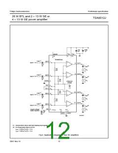
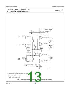
(1) Advised when driven with hard clipping input signals.
(2) For frequencies down to 20 Hz:
Cout = 4700 µF at RL1 = 2 Ω.
Cout = 2200 µF at RL1 = 4 Ω.
Fig.7 Application diagram for one BTL amplifier and two SE amplifiers.
13
2001 Nov 16

 NXP [ NXP ]