Philips Semiconductors
Preliminary specification
26 W BTL and 2 × 13 W SE or
4 × 13 W SE power amplifier
TDA8512J
MGW436
MGW435
0
10
handbook, halfpage
handbook, halfpage
SVRR
(dB)
THD
(%)
−20
−40
1
(1)
(2)
−1
10
(1)
(2)
−60
(3)
(4)
−2
−80
10
10
−2
−1
2
−2
−1
2
10
1
10
10
10
10
1
10
10
f (kHz)
f (kHz)
i
i
SE mode.
(3) Operating mode channel 2.
(4) Operating mode channel 1.
SE mode.
(1) Mute mode channel 2.
(2) Mute mode channel 1.
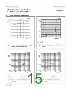
(1) RL = 4 Ω.
(2) RL = 2 Ω.
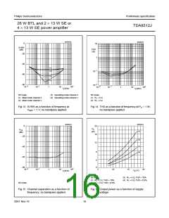
Fig.13 SVRR as a function of frequency at
VREF = 1 V; no bandpass applied.
Fig.14 THD as a function of frequency at Po = 1 W;
no bandpass applied.
MGW443
MGW444
0
20
handbook, halfpage
handbook, halfpage
P
α
(dB)
o
cs
(1)
(2)
(W)
16
−20
12
8
−40
−60
−80
(3)
(4)
4
0
−2
−1
2
5
10
15
20
10
10
1
10
10
V
(V)
f (kHz)
P
i
SE mode.
(3) RL = 4 Ω; THD = 10%.
(4) RL = 4 Ω; THD = 0.5%.
(1) RL = 2 Ω; THD = 10%.
(2) RL = 2 Ω; THD = 0.5%.
SE mode.
Fig.15 Channel separation as a function of
frequency; no bandpass applied.
Fig.16 Output power as a function of supply
voltage.
2001 Nov 16
16

 NXP [ NXP ]