Philips Semiconductors
Product specification
Dual asynchronous receiver/transmitter (DUART)
SCC2692
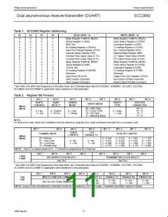
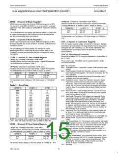
CSRB[3:0] – Channel B Transmitter Clock Select
This field selects the baud rate clock for the Channel B transmitter.
The field definition is as shown in Table 3, except as follows:
MR1B – Channel B Mode Register 1
MR1B is accessed when the Channel B MR pointer points to MR1.
The pointer is set to MR1 by RESET or by a ‘set pointer’ command
applied via CRB. After reading or writing MR1B, the pointer will point
to MR2B.
CSRB[3:0]
ACR[7] = 0
ACR[7] = 1
1110
1111
IP5-16X
IP5-1X
IP5-16X
IP5-1X
The bit definitions for this register are identical to MR1A, except that
all control actions apply to the Channel B receiver and transmitter
and the corresponding inputs and outputs.
The transmitter clock is always a 16X clock except for CSRB[3:0] =
1111.
MR2B – Channel B Mode Register 2
MR2B is accessed when the Channel B MR pointer points to MR2,
which occurs after any access to MR1B. Accesses to MR2B do not
change the pointer.
CRA – Channel A Command Register
CRA is a register used to supply commands to Channel A. Multiple
commands can be specified in a single write to CRA as long as the
commands are non-conflicting, e.g., the ‘enable transmitter’ and
‘reset transmitter’ commands cannot be specified in a single
command word.
The bit definitions for mode register are identical to the bit
definitions for MR2A, except that all control actions apply to the
Channel B receiver and transmitter and the corresponding inputs
and outputs.
CRA[7:4] – Miscellaneous Commands
Sequential writes to CR(7:4) should be separated by three edges of
the X1 clock.
CSRA – Channel A Clock Select Register
CSRA[7:4] – Channel A Receiver Clock Select
This field selects the baud rate clock for the Channel A transmitter.
The field definition is shown in Table 3.
The encoded value of this field may be used to specify a single
command as follows:
0000 No command.
0001 Reset MR pointer. Causes the Channel A MR pointer to point
to MR1.
0010 Reset receiver. Resets the Channel A receiver as if a hard-
ware reset had been applied. The receiver is disabled and the
FIFO is flushed.
0011 Reset transmitter. Resets the Channel A transmitter as if a
hardware reset had been applied.
CSRA[3:0] – Channel A Transmitter Clock Select
This field selects the baud rate clock for the Channel A transmitter.
The field definition is as shown in Table 3, except as follows:
CSRA[3:0]
ACR[7] = 0
ACR[7] = 1
1110
1111
IP3-16X
IP3-1X
IP3-16X
IP3-1X
The transmitter clock is always a 16X clock except for CSRA[3:0] =
1111.
0100 Reset error status. Clears the Channel A Received Break,
Parity Error, and Overrun Error bits in the status register
(SRA[7:4]). Used in character mode to clear OE status (al-
though RB, PE and FE bits will also be cleared) and in block
mode to clear all error status after a block of data has been
received.
0101 Reset Channel A break change interrupt. Causes the Chan-
nel A break detect change bit in the interrupt status register
(ISR[2]) to be cleared to zero.
0110 Start break. Forces the TxDA output Low (spacing). If the
transmitter is empty the start of the break condition will be
delayed up to two bit times. If the transmitter is active the
break begins when transmission of the character is com-
pleted. If a character is in the THR, the start of the break will
be delayed until that character, or any other loaded subse-
quently are transmitted. The transmitter must be enabled for
this command to be accepted.
0111 Stop break. The TxDA line will go High (marking) within two
bit times. TxDA will remain High for one bit time before the
next character, if any, is transmitted.
1000 Assert RTSN. Causes the RTSN output to be asserted (Low).
1001 Negate RTSN. Causes the RTSN output to be negated
(High).
1010 Set Timeout Mode On. The receiver in this channel will restart
the C/T as each receive character is transferred from the shift
register to the RHR. The C/T is placed in the counter mode,
the START/STOP counter commands are disabled, the
counter is stopped, and the Counter Ready Bit, ISR[3], is
reset. The counter will not start until the first character is re-
ceived after the command is issued.
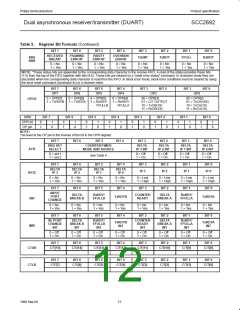
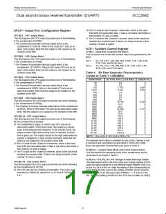
Table 3. Baud Rate
CSRA[7:4]
ACR[7] = 0
ACR[7] = 1
0000
0001
0010
0011
0100
0101
0110
0111
1000
1001
50
110
134.5
200
300
600
1,200
1,050
2,400
4,800
75
110
134.5
150
300
600
1,200
2,000
2,400
4,800
1010
1011
1100
1101
1110
1111
7,200
9,600
38.4K
Timer
IP4-16X
1,800
9,600
19.2K
Timer
IP4-16X
IP4-1X
IP4-1X
NOTE: The receiver clock is always a 16X clock except for CSRA[7:4]
= 1111. Also, see Table 6 for baud rates available in BRG Test.
CSRB – Channel B Clock Select Register
CSRB[7:4] – Channel B Receiver Clock Select
This field selects the baud rate clock for the Channel B receiver.
The field definition is as shown in Table 3, except as follows:
1011 Not used.
CSRB[7:4]
ACR[7] = 0
ACR[7] = 1
1100 Disable Timeout Mode. This command returns control of the
C/T to the regular START/STOP counter commands. It does
not stop the counter, or clear any pending interrupts. After
disabling the timeout mode, a ‘Stop Counter’ command
should be issued to reset the ISR(3) bit.
1110
1111
IP6-16X
IP6-1X
IP6-16X
IP6-1X
The receiver clock is always a 16X clock except for CSRB[7:4] = 1111.
1998 Sep 04
1101 Not used.
15

 NXP [ NXP ]