Philips Semiconductors
Product specification
Dual asynchronous receiver/transmitter (DUART)
SCC2692
1. Received data is re-clocked and retransmitted on the TxDA out-
put.
1. Program the auto-reset mode: MR2[5]=1
2. Enable transmitter, if not already enabled
3. Assert RTSN via command
4. Send message
5. After the last character of the message is loaded to the THR,
disable the transmitter. (If the transmitter is underrun, a special
case exists. See note below.)
2. The receive clock is used for the transmitter.
3. Received data is not sent to the local CPU, and the error status
conditions are inactive.
4. The received parity is not checked and is not regenerated for
transmission, i.e., transmitted parity is as received.
6. The last character will be transmitted and the RTSN will be reset
one bit time after the last stop bit is sent.
5. The receiver must be enabled.
NOTE: The transmitter is in an underrun condition when both the
TxRDY and the TxEMT bits are set. This condition also exists
immediately after the transmitter is enabled from the disabled or
reset state. When using the above procedure with the transmitter in
the underrun condition, the issuing of the transmitter disable must be
delayed from the loading of a single, or last, character until the
TxRDY becomes active again after the character is loaded.
6. Character framing is not checked, and the stop bits are retrans-
mitted as received.
7. A received break is echoed as received until the next valid start
bit is detected.
The user must exercise care when switching into and out of the
various modes. The selected mode will be activated immediately
upon mode selection, even if this occurs in the middle of a received
or transmitted character. Likewise, if a mode is deselected the
device will switch out of the mode immediately. An exception to this
is switching out of autoecho or remote loopback modes: if the
de-selection occurs just after the receiver has sampled the stop bit
(indicated in autoecho by assertion of RxRDY), and the transmitter
is enabled, the transmitter will remain in autoecho mode until the
entire stop has been re-transmitted.
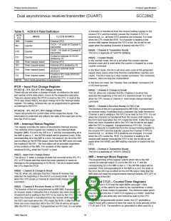
MR2A[4] – Channel A Clear-to-Send Control
If this bit is 0, CTSAN has no effect on the transmitter. If this bit is a
1, the transmitter checks the state of CTSAN (IPO) each time it is
ready to send a character. If IPO is asserted (Low), the character is
transmitted. If it is negated (High), the TxDA output remains in the
marking state and the transmission is delayed until CTSAN goes
low. Changes in CTSAN while a character is being transmitted do
not affect the transmission of that character..
MR2A[5] – Channel A Transmitter Request-to-Send Control
CAUTION: When the transmitter controls the OP pin (usually used
for the RTSN signal) the meaning of the pin is not RTSN at all!
Rather, it signals that the transmitter has finished the transmission
(i.e., end of block).
MR2A[3:0] – Channel A Stop Bit Length Select
This field programs the length of the stop bit appended to the
transmitted character. Stop bit lengths of 9/16 to 1 and 1-9/16 to 2
bits, in increments of 1/16 bit, can be programmed for character
lengths of 6, 7, and 8 bits. For a character lengths of 5 bits, 1-1/16 to
2 stop bits can be programmed in increments of 1/16 bit. In all
cases, the receiver only checks for a ‘mark’ condition at the center
of the first stop bit position (one bit time after the last data bit, or
after the parity bit is enabled).
This bit allows deactivation of the RTSN output by the transmitter.
This output is manually asserted and negated by the appropriate
commands issued via the command register. MR2[5] set to 1
caused the RTSN to be reset automatically one bit time after the
character(s) in the transmit shift register and in the THR (if any) are
completely transmitted (including the programmed number of stop
bits) if a previously issued transmitter disable is pending. This
feature can be used to automatically terminate the transmission as
follows:
If an external 1X clock is used for the transmitter, MR2A[3] = 0
selects one stop bit and MR2A[3] = 1 selects two stop bits to be
transmitted.
14
1998 Sep 04

 NXP [ NXP ]