Philips Semiconductors
Product specification
Dual asynchronous receiver/transmitter (DUART)
SCC2692
data clock. The formula for calculating the divisor n to load to the
CTUR and CTLR for a particular 1X data clock is shown below:
In the counter mode, the C/T counts down the number of pulses
loaded into CTUR and CTLR by the CPU. Counting begins upon
receipt of a start counter command. Upon reaching terminal count
H‘0000’, the counter ready interrupt bit (ISR[3]) is set. The counter
continues counting past the terminal count until stopped by the CPU.
If OP3 is programmed to be the output of the C/T, the output
remains High until terminal count is reached, at which time it goes
Low. The output returns to the High state and ISR[3] is cleared when
the counter is stopped by a stop counter command. The CPU may
change the values of CTUR and CTLR at any time, but the new
count becomes effective only on the next start counter commands. If
new values have not been loaded, the previous count values are
preserved and used for the next count cycle
counter clock frequency
n +
16 x 2 x baud rate desired
Often this division will result in a non-integer number; 26.3, for
example. One can only program integer numbers in a digital divider.
Therefore, 26 would be chosen. This gives a baud rate error of
0.3/26.3 which is 1.14%; well within the ability asynchronous mode
of operation.
If the value in CTUR and CTLR is changed, the current half-period
will not be affected, but subsequent half periods will be. The C/T will
not be running until it receives an initial ‘Start Counter’ command
(read at address A3-A0 = 1110). After this, while in timer mode, the
C/T will run continuously. Receipt of a start counter command (read
with A3-A0 = 1110) causes the counter to terminate the current
timing cycle and to begin a new cycle using the values in CTUR and
CTLR.
In the counter mode, the current value of the upper and lower 8 bits
of the counter (CTU, CTL) may be read by the CPU. It is
recommended that the counter be stopped when reading to prevent
potential problems which may occur if a carry from the lower 8 bits
to the upper 8 bits occurs between the times that both halves of the
counter are read. However, note that a subsequent start counter
command will cause the counter to begin a new count cycle using
the values in CTUR and CTLR.
The counter ready status bit (ISR[3]) is set once each cycle of the
square wave. The bit is reset by a stop counter command (read with
A3-A0 = H‘F’). The command however, does not stop the C/T. The
generated square wave is output on OP3 if it is programmed to be
the C/T output.
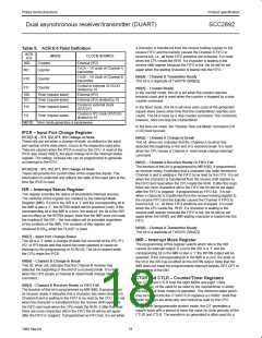
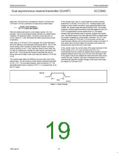
RESETN
t
RES
SD00133
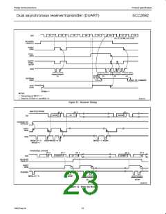
Figure 3. Reset Timing
19
1998 Sep 04

 NXP [ NXP ]