Philips Semiconductors
Product specification
Dual asynchronous receiver/transmitter (DUART)
SCC2692
10 The 1X clock for the Channel A transmitter, which is the clock
that shifts the transmitted data. If data is not being transmitted, a
free running 1X clock is output.
11 The 1X clock for the Channel A receiver, which is the clock that
samples the received data. If data is not being received, a free
running 1X clock is output.
OPCR – Output Port Configuration Register
OPCR[7] – OP7 Output Select
This bit programs the OP7 output to provide one of the following:
0 The complement of OPR[7].
1 The Channel B transmitter interrupt output which is the
complement of TxRDYB. When in this mode OP7 acts as an
open- drain output. Note that this output is not masked by the
contents of the IMR.
ACR – Auxiliary Control Register
ACR[7] – Baud Rate Generator Set Select
This bit selects one of two sets of baud rates to be generated by the
BRG:
OPCR[6] – OP6 Output Select
This bit programs the OP6 output to provide one of the following:
0 The complement of OPR[6].
1 The Channel A transmitter interrupt output which is the
complement of TxRDYA. When in this mode OP6 acts as an
open- drain output. Note that this output is not masked by the
contents of the IMR.
Set 1:
50, 110, 134.5, 200, 300, 600, 1.05K, 1.2K, 2.4K, 4.8K,
7.2K, 9.6K, and 38.4K baud.
Set 2:
75, 110, 134.5, 150, 300, 600, 1.2K, 1.8K, 2.0K, 2.4K,
4.8K, 9.6K, and 19.2K baud.
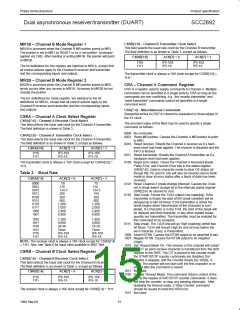
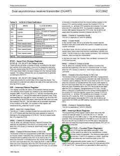
Table 4. Bit Rate Generator Characteristics
Crystal or Clock = 3.6864MHz
OPCR[5] – OP5 Output Select
BAUD RATE
ACTUAL 16X CLOCK (kHz)
ERROR (%)
This bit programs the OP5 output to provide one of the following:
0 The complement of OPR[5].
1 The Channel B transmitter interrupt output which is the
complement of ISR[5]. When in this mode OP5 acts as an
open-drain output. Note that this output is not masked by the
contents of the IMR.
50
75
110
134.5
150
200
0.8
1.2
1.759
2.153
2.4
0
0
-0.069
0.059
0
0
3.2
300
600
4.8
9.6
16.756
19.2
28.8
32.056
38.4
76.8
115.2
153.6
230.4
307.2
460.8
614.4
921.2
1,843.2
0
0
OPCR[4] – OP4 Output Select
This field programs the OP4 output to provide one of the following:
0 The complement of OPR[4].
1 The Channel A receiver interrupt output which is the complement
of ISR[1]. When in this mode OP4 acts as an open-drain output.
Note that this output is not masked by the contents of the IMR.
1050
1200
1800
2000
2400
4800
7200
9600
14.4K
19.2K
28.8K
38.4K
57.6K
115.2K
-0.260
0
0
0.175
0
0
0
0
0
0
0
0
0
0
OPCR[3:2] – OP3 Output Select
This bit programs the OP3 output to provide one of the following:
00 The complement of OPR[3].
01 The counter/timer output, in which case OP3 acts as an
open-drain output. In the timer mode, this output is a square
wave at the programmed frequency. In the counter mode, the
output remains High until terminal count is reached, at which
time it goes Low. The output returns to the High state when the
counter is stopped by a stop counter command. Note that this
output is not masked by the contents of the IMR.
10 The 1X clock for the Channel B transmitter, which is the clock
that shifts the transmitted data. If data is not being transmitted, a
free running 1X clock is output.
NOTE: Duty cycle of 16X clock is 50% ±1%.
The selected set of rates is available for use by the Channel A and
B receivers and transmitters as described in CSRA and CSRB.
Baud rate generator characteristics are given in Table 4.
ACR[6:4] – Counter/Timer Mode And Clock Source Select
This field selects the operating mode of the counter/timer and its
clock source as shown in Table 5.
11 The 1X clock for the Channel B receiver, which is the clock that
samples the received data. If data is not being received, a free
running 1X clock is output.
ACR[3:0] – IP3, IP2, IP1, IP0 Change-of-State Interrupt Enable
This field selects which bits of the input port change register (IPCR)
cause the input change bit in the interrupt status register (ISR[7]) to
be set. If a bit is in the ‘on’ state the setting of the corresponding bit
in the IPCR will also result in the setting of ISR[7], which results in
the generation of an interrupt output if IMR[7] = 1. If a bit is in the
‘off’ state, the setting of that bit in the IPCR has no effect on ISR[7].
OPCR[1:0] – OP2 Output Select
This field programs the OP2 output to provide one of the following:
00 The complement of OPR[2].
01 The 16X clock for the Channel A transmitter. This is the clock
selected by CSRA[3:0], and will be a 1X clock if CSRA[3:0] =
1111.
17
1998 Sep 04

 NXP [ NXP ]