Philips Semiconductors
Product specification
Dual asynchronous receiver/transmitter (DUART)
SCC2692
1110 Power Down Mode On. In this mode, the DUART oscillator is
stopped and all functions requiring this clock are suspended.
The execution of commands other than disable power down
mode (1111) requires a X1/CLK. While in the power down
mode, do not issue any commands to the CR except the
disable power down mode command. The contents of all
registers will be saved while in this mode. It is recommended
that the transmitter and receiver be disabled prior to placing
the DUART into power down mode. This command is in CRA
only.
SRA[6] – Channel A Framing Error
This bit, when set, indicates that a stop bit was not detected when
the corresponding data character in the FIFO was received. The
stop bit check is made in the middle of the first stop bit position.
SRA[5] – Channel A Parity Error
This bit is set when the ‘with parity’ or ‘force parity’ mode is
programmed and the corresponding character in the FIFO was
received with incorrect parity.
In the special multidrop mode the parity error bit stores the receive
A/D bit.
1111 Disable Power Down Mode. This command restarts the oscil-
lator. After invoking this command, wait for the oscillator to
start up before writing further commands to the CR. This
command is in CRA only.
SRA[4] – Channel A Overrun Error
This bit, when set, indicates that one or more characters in the
received data stream have been lost. It is set upon receipt of a new
character when the FIFO is full and a character is already in the
receive shift register waiting for an empty FIFO position. When this
occurs, the character in the receive shift register (and its break
detect, parity error and framing error status, if any) is lost.
CRA[3] – Disable Channel A Transmitter
This command terminates transmitter operation and resets the
TxDRY and TxEMT status bits. However, if a character is being
transmitted or if a character is in the THR when the transmitter is
disabled, the transmission of the character(s) is completed before
assuming the inactive state.
This bit is cleared by a ‘reset error status’ command.
CRA[2] – Enable Channel A Transmitter
Enables operation of the Channel A transmitter. The TxRDY status
bit will be asserted.
SRA[3] – Channel A Transmitter Empty (TxEMTA)
This bit will be set when the transmitter underruns, i.e., both the
TxEMT and TxRDY bits are set. This bit and TxRDY are set when
the transmitter is first enabled and at any time it is re-enabled after
either (a) reset, or (b) the transmitter has assumed the disabled
state. It is always set after transmission of the last stop bit of a
character if no character is in the THR awaiting transmission.
CRA[1] – Disable Channel A Receiver
This command terminates operation of the receiver immediately – a
character being received will be lost. The command has no effect on
the receiver status bits or any other control registers. If the special
multidrop mode is programmed, the receiver operates even if it is
disabled. See Operation section.
It is reset when the THR is loaded by the CPU, a pending
transmitter disable is executed, the transmitter is reset, or the
transmitter is disabled while in the underrun condition.
CRA[0] – Enable Channel A Receiver
Enables operation of the Channel A receiver. If not in the special
wake-up mode, this also forces the receiver into the search for start
bit state.
SRA[2] – Channel A Transmitter Ready (TxRDYA)
This bit, when set, indicates that the THR is empty and ready to be
loaded with a character. This bit is cleared when the THR is loaded
by the CPU and is set when the character is transferred to the
transmit shift register. TxRDY is reset when the transmitter is
disabled and is set when the transmitter is first enabled, e.g.,
characters loaded into the THR while the transmitter is disabled will
not be transmitted.
CRB – Channel B Command Register
CRB is a register used to supply commands to Channel B. Multiple
commands can be specified in a single write to CRB as long as the
commands are non-conflicting, e.g., the ‘enable transmitter’ and
‘reset transmitter’ commands cannot be specified in a single
command word.
SRA[1] – Channel A FIFO Full (FFULLA)
The bit definitions for this register are identical to the bit definitions
for CRA, with the exception of commands “Ex” and “Fx” which are
used for power downmode. These two commands are not used in
CRB. All other control actions that apply to CRA also apply to CRB.
This bit is set when a character is transferred from the receive shift
register to the receive FIFO and the transfer causes the FIFO to
become full, i.e., all three FIFO positions are occupied. It is reset
when the CPU reads the RHR. If a character is waiting in the
receive shift register because the FIFO is full, FFULL will not be
reset when the CPU reads the RHR.
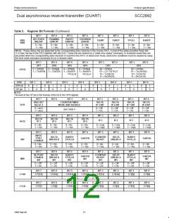
SRA – Channel A Status Register
SRA[7] – Channel A Received Break
SRA[0] – Channel A Receiver Ready (RxRDYA)
This bit indicates that a character has been received and is waiting
in the FIFO to be read by the CPU. It is set when the character is
transferred from the receive shift to the FIFO and reset when the
CPU reads the RHR, if after this read there are not more characters
still in the FIFO.
This bit indicates that an all zero character of the programmed
length has been received without a stop bit. Only a single FIFO
position is occupied when a break is received: further entries to the
FIFO are inhibited until the RxDA line returns to the marking state
for at least one-half a bit time two successive edges of the internal
or external 1X clock. This will usually require a high time of one
X1 clock period or 3 X1 edges since the clock of the controller
is not synchronous to the X1 clock.
SRB – Channel B Status Register
The bit definitions for this register are identical to the bit definitions
for SRA, except that all status applies to the Channel B receiver and
transmitter and the corresponding inputs and outputs.
When this bit is set, the Channel A ‘change in break’ bit in the ISR
(ISR[2]) is set. ISR[2] is also set when the end of the break
condition, as defined above, is detected.
The break detect circuitry can detect breaks that originate in the
middle of a received character. However, if a break begins in the
middle of a character, it must persist until at least the end of the next
character time in order for it to be detected.
16
1998 Sep 04

 NXP [ NXP ]