Philips Semiconductors
Product specification
Dual asynchronous receiver/transmitter (DUART)
SCC2692
MR1A[4:3| – Channel A Parity Mode Select
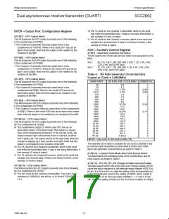
PROGRAMMING
If ‘with parity’ or ‘force parity’ is selected a parity bit is added to the
transmitted character and the receiver performs a parity check on
incoming data MR1A[4:3] = 11 selects Channel A to operate in the
special multidrop mode described in the Operation section.
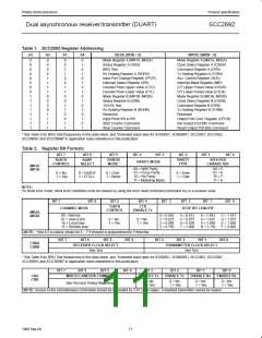
The operation of the DUART is programmed by writing control words
into the appropriate registers. Operational feedback is provided via
status registers which can be read by the CPU. The addressing of
the registers is described in Table 1.
The contents of certain control registers are initialized to zero on
RESET. Care should be exercised if the contents of a register are
changed during operation, since certain changes may cause
operational problems.
MR1A[2] – Channel A Parity Type Select
This bit selects the parity type (odd or even) if the ‘with parity’ mode
is programmed by MR1A[4:3], and the polarity of the forced parity bit
if the ‘force parity’ mode is programmed. It has no effect if the ‘no
parity’ mode is programmed. In the special multidrop mode it selects
the polarity of the A/D bit.
For example, changing the number of bits per character while the
transmitter is active may cause the transmission of an incorrect
character. In general, the contents of the MR, the CSR, and the
OPCR should only be changed while the receiver(s) and
transmitter(s) are not enabled, and certain changes to the ACR
should only be made while the C/T is stopped.
MR1A[1:0] – Channel A Bits Per Character Select
This field selects the number of data bits per character to be
transmitted and received. The character length does not include the
start, parity, and stop bits.
Mode registers 1 and 2 of each channel are accessed via
independent auxiliary pointers. The pointer is set to MR1X by
RESET or by issuing a ‘reset pointer’ command via the
corresponding command register. Any read or write of the mode
register while the pointer is at MR1X, switches the pointer to MR2X.
The pointer then remains at MR2X, so that subsequent accesses
are always to MR2X unless the pointer is reset to MR1X as
described above.
MR2A – Channel A Mode Register 2
MR2A is accessed when the Channel A MR pointer points to MR2,
which occurs after any access to MR1A. Accesses to MR2A do not
change the pointer.
MR2A[7:6] – Channel A Mode Select
Each channel of the DUART can operate in one of four modes.
MR2A[7:6] = 00 is the normal mode, with the transmitter and
receiver operating independently. MR2A[7:6] = 01 places the
channel in the automatic echo mode, which automatically
re-transmits the received data. The following conditions are true
while in automatic echo mode:
Mode, command, clock select, and status registers are duplicated
for each channel to provide total independent operation and control.
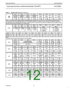
Refer to Table 2 for register bit descriptions. The reserved registers
at addresses H‘02’ and H‘OA’ should never be read during normal
operation since they are reserved for internal diagnostics.
1. Received data is re-clocked and retransmitted on the TxDA out-
put.
MR1A – Channel A Mode Register 1
MR1A is accessed when the Channel A MR pointer points to MR1.
The pointer is set to MR1 by RESET or by a ‘set pointer’ command
applied via CRA. After reading or writing MR1A, the pointer will point
to MR2A.
2. The receive clock is used for the transmitter.
3. The receiver must be enabled, but the transmitter need not be
enabled.
4. The Channel A TxRDY and TxEMT status bits are inactive.
5. The received parity is checked, but is not regenerated for trans-
mission, i.e., transmitted parity bit is as received.
MR1A[7] – Channel A Receiver Request-to-Send Control
This bit controls the deactivation of the RTSAN output (OP0) by the
receiver. This output is normally asserted by setting OPR[0] and
negated by resetting OPR[0]. MR1A[7] = 1 causes RTSAN to be
negated upon receipt of a valid start bit if the Channel A FIFO is full.
However, OPR[0] is not reset and RTSAN will be asserted again
when an empty FIFO position is available. This feature can be used
for flow control to prevent overrun in the receiver by using the
RTSAN output signal to control the CTSN input of the transmitting
device.
6. Character framing is checked, but the stop bits are retransmitted
as received.
7. A received break is echoed as received until the next valid start
bit is detected.
8. CPU to receiver communication continues normally, but the CPU
to transmitter link is disabled.
Two diagnostic modes can also be configured. MR2A[7:6] = 10
selects local loopback mode. In this mode:
1. The transmitter output is internally connected to the receiver
input.
MR1A[6] – Channel A Receiver Interrupt Select
This bit selects either the Channel A receiver ready status (RxRDY)
or the Channel A FIFO full status (FFULL) to be used for CPU
interrupts. It also causes the selected bit to be output on OP4 if it is
programmed as an interrupt output via the OPCR.
2. The transmit clock is used for the receiver.
3. The TxDA output is held High.
4. The RxDA input is ignored.
MR1A[5] – Channel A Error Mode Select
This bit selects the operating mode of the three FIFOed status bits
(FE, PE, received break) for Channel A. In the ‘character’ mode,
status is provided on a character-by-character basis; the status
applies only to the character at the top of the FIFO. In the ‘block’
mode, the status provided in the SR for these bits is the
accumulation (logical-OR) of the status for all characters coming to
the top of the FIFO since the last ‘reset error’ command for Channel
A was issued.
5. The transmitter must be enabled, but the receiver need not be
enabled.
6. CPU to transmitter and receiver communications continue nor-
mally.
The second diagnostic mode is the remote loopback mode, selected
by MR2A[7:6] = 11. In this mode:
13
1998 Sep 04

 NXP [ NXP ]