Philips Semiconductors
Preliminary data
Low power, low price, low pin count (20 pin)
microcontroller with 4 kbyte OTP
87LPC764
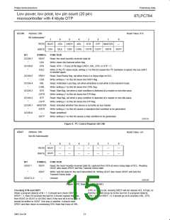
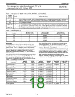
Table 1. Interaction of TIRUN with SLAVEN, MASTRQ, and MASTER
SLAVEN,
MASTRQ,
MASTER
TIRUN
OPERATING MODE
2
2
The I C interface is disabled. Timer I is cleared and does not run. This is the state assumed after a reset. If an I C
All 0
All 0
0
1
0
2
application wants to ignore the I C at certain times, it should write SLAVEN, MASTRQ, and TIRUN all to zero.
2
The I C interface is disabled.
2
The I C interface is enabled. The 3 low-order bits of Timer I run for min-time generation, but the hi-order bits do
Any or all 1
2
2
not, so that there is no checking for I C being “hung.” This configuration can be used for very slow I C operation.
2
2
The I C interface is enabled. Timer I runs during frames on the I C, and is cleared by transitions on SCL, and by
Any or all 1
1
2
Start and Stop conditions. This is the normal state for I C operation.
Table 2. CT1, CT0 Values
Min Time Count
(Machine Cycles)
CPU Clock Max
(for 100 kHz I C)
Timeout Period
(Machine Cycles)
CT1, CT0
2
1 0
0 1
0 0
1 1
7
6
5
4
8.4 MHz
7.2 MHz
6.0 MHz
4.8 MHz
1023
1022
1021
1020
of the same or lower priority. The highest priority interrupt service
cannot be interrupted by any other interrupt source. So, if two
requests of different priority levels are received simultaneously, the
request of higher priority level is serviced.
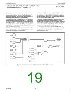
Interrupts
The 87LPC764 uses a four priority level interrupt structure. This
allows great flexibility in controlling the handling of the 87LPC764’s many
interrupt sources. The 87LPC764 supports up to 12 interrupt sources.
If requests of the same priority level are received simultaneously, an
internal polling sequence determines which request is serviced. This
is called the arbitration ranking. Note that the arbitration ranking is
only used to resolve simultaneous requests of the same priority level.
Each interrupt source can be individually enabled or disabled by
setting or clearing a bit in registers IEN0 or IEN1. The IEN0
register also contains a global disable bit, EA, which disables all
interrupts at once.
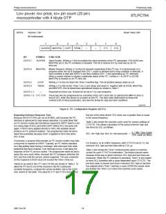
Table 3 summarizes the interrupt sources, flag bits, vector
addresses, enable bits, priority bits, arbitration ranking, and whether
each interrupt may wake up the CPU from Power Down mode.
Each interrupt source can be individually programmed to one of four
priority levels by setting or clearing bits in the IP0, IP0H, IP1, and
IP1H registers. An interrupt service routine in progress can be
interrupted by a higher priority interrupt, but not by another interrupt
Table 3. Summary of Interrupts
Interrupt
Flag Bit(s)
Vector
Address
Interrupt
Enable Bit(s)
Interrupt
Priority
Arbitration
Ranking
Power Down
Wakeup
Description
External Interrupt 0
Timer 0 Interrupt
IE0
TF0
0003h
000Bh
0013h
001Bh
0023h
002Bh
0033h
003Bh
0043h
0053h
0063h
0073h
EX0 (IEN0.0)
ET0 (IEN0.1)
EX1 (IEN0.2)
ET1 (IEN0.3)
ES (IEN0.4)
EBO (IEN0.5)
EI2 (IEN1.0)
EKB (IEN1.1)
EC2 (IEN1.2)
EWD (IEN0.6)
EC1 (IEN1.5)
ETI (IEN1.7)
IP0H.0, IP0.0
IP0H.1, IP0.1
IP0H.2, IP0.2
IP0H.3, IP0.3
IP0H.4, IP0.4
IP0H.5, IP0.5
IP1H.0, IP1.0
IP1H.1, IP1.1
IP1H.2, IP1.2
IP0H.6, IP0.6
IP1H.5, IP1.5
IP1H.7, IP1.7
1 (highest)
Yes
No
4
External Interrupt 1
Timer 1 Interrupt
IE1
6
Yes
No
TF1
9
Serial Port Tx and Rx
Brownout Detect
TI & RI
BOD
ATN
11
No
2
Yes
No
2
I C Interrupt
5
KBI Interrupt
KBF
7
Yes
Yes
Yes
Yes
No
Comparator 2 interrupt
Watchdog Timer
CMF2
WDOVF
CMF1
–
10
3
8
Comparator 1 interrupt
Timer I interrupt
12 (lowest)
15
2001 Oct 26

 NXP [ NXP ]