Philips Semiconductors
Preliminary data
Low power, low price, low pin count (20 pin)
microcontroller with 4 kbyte OTP
87LPC764
ARL
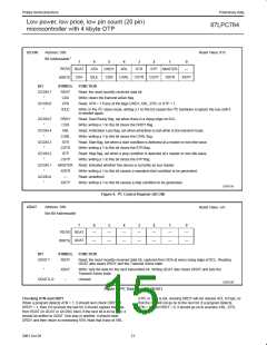
“Arbitration Loss” is 1 when transmit Active was set, but
this device lost arbitration to another transmitter.
Transmit Active is cleared when ARL is 1. There are
four separate cases in which ARL is set.
Regarding Transmit Active
Transmit Active is set by writing the I2DAT register, or by writing
I2CON with XSTR = 1 or XSTP = 1. The I C interface will only drive
the SDA line low when Transmit Active is set, and the ARL bit will
only be set to 1 when Transmit Active is set. Transmit Active is
cleared by reading the I2DAT register, or by writing I2CON with CXA
= 1. Transmit Active is automatically cleared when ARL is 1.
2
1. If the program sent a 1 or repeated start, but another
device sent a 0, or a stop, so that SDA is 0 at the rising
edge of SCL. (If the other device sent a stop, the setting
of ARL will be followed shortly by STP being set.)
2
IDLE
Writing 1 to “IDLE” causes a slave’s I C hardware to
ignore the I C until the next start condition (but if
2
2. If the program sent a 1, but another device sent a
repeated start, and it drove SDA low before SCL
could be driven low. (This type of ARL is always
accompanied by STR = 1.)
MASTRQ is 1, then a stop condition will cause this
device to become a master).
CDR
Writing a 1 to “Clear Data Ready” clears DRDY.
(Reading or writing the I2DAT register also does this.)
3. In master mode, if the program sent a repeated start,
but another device sent a 1, and it drove SCL low
before this device could drive SDA low.
CARL
CSTR
CSTP
Writing a 1 to “Clear Arbitration Loss” clears the ARL bit.
Writing a 1 to “Clear STaRt” clears the STR bit.
4. In master mode, if the program sent stop, but it could
not be sent because another device sent a 0.
Writing a 1 to “Clear SToP” clears the STP bit. Note that
if one or more of DRDY, ARL, STR, or STP is 1, the low
time of SCL is stretched until the service routine
responds by clearing them.
2
STR
STP
“STaRt” is set to a 1 when an I C start condition is
detected at a non-idle slave or at a master. (STR is not
set when an idle slave becomes active due to a start
bit; the slave has nothing useful to do until the rising
edge of SCL sets DRDY.)
XSTR
Writing 1s to “Xmit repeated STaRt” and CDR tells the
2
I C hardware to send a repeated start condition. This
should only be at a master. Note that XSTR need not
and should not be used to send an “initial”
2
“SToP” is set to 1 when an I C stop condition is
2
detected at a non-idle slave or at a master. (STP is not
set for a stop condition at an idle slave.)
(non-repeated) start; it is sent automatically by the I C
hardware. Writing XSTR = 1 includes the effect of
writing I2DAT with XDAT = 1; it sets Transmit Active
and releases SDA to high during the SCL low time.
MASTER “MASTER” is 1 if this device is currently a master on
2
the I C. MASTER is set when MASTRQ is 1 and the
2
After SCL goes high, the I C hardware waits for the
bus is not busy (i.e., if a start bit hasn’t been
received since reset or a “Timer I” time-out, or if a stop
has been received since the last start). MASTER is
cleared when ARL is set, or after the software writes
MASTRQ = 0 and then XSTP = 1.
suitable minimum time and then drives SDA low to
make the start condition.
2
XSTP
Writing 1s to “Xmit SToP” and CDR tells the I C
hardware to send a stop condition. This should only be
done at a master. If there are no more messages to
initiate, the service routine should clear the MASTRQ
bit in I2CFG to 0 before writing XSTP with 1. Writing
XSTP = 1 includes the effect of writing I2DAT with
XDAT = 0; it sets Transmit Active and drives SDA low
Writing I2CON
2
Typically, for each bit in an I C message, a service routine waits for
ATN = 1. Based on DRDY, ARL, STR, and STP, and on the current
bit position in the message, it may then write I2CON with one or
more of the following bits, or it may read or write the I2DAT register.
2
during the SCL low time. After SCL goes high, the I C
hardware waits for the suitable minimum time and then
releases SDA to high to make the stop condition.
CXA
Writing a 1 to “Clear Xmit Active” clears the Transmit
Active state. (Reading the I2DAT register also does this.)
13
2001 Oct 26

 NXP [ NXP ]