Philips Semiconductors
Preliminary data
Low power, low price, low pin count (20 pin)
microcontroller with 4 kbyte OTP
87LPC764
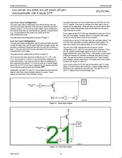
input and output without the need to reconfigure the port. This is
possible because when the port outputs a logic high, it is weakly
driven, allowing an external device to pull the pin low. When the pin
is pulled low, it is driven strongly and able to sink a fairly large
current. These features are somewhat similar to an open drain
output except that there are three pull-up transistors in the
quasi-bidirectional output that serve different purposes.
I/O Ports17
The 87LPC764 has 3 I/O ports, port 0, port 1, and port 2. The exact
number of I/O pins available depend upon the oscillator and reset
options chosen. At least 15 pins of the 87LPC764 may be used as
I/Os when a two-pin external oscillator and an external reset circuit
are used. Up to 18 pins may be available if fully on-chip oscillator
and reset configurations are chosen.
One of these pull-ups, called the “very weak” pull-up, is turned on
whenever the port latch for the pin contains a logic 1. The very weak
pull-up sources a very small current that will pull the pin high if it is
left floating.
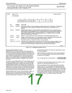
All but three I/O port pins on the 87LPC764 may be software
configured to one of four types on a bit-by-bit basis, as shown in
Table 4. These are: quasi-bidirectional (standard 80C51 port
outputs), push-pull, open drain, and input only. Two configuration
registers for each port choose the output type for each port pin.
A second pull-up, called the “weak” pull-up, is turned on when the
port latch for the pin contains a logic 1 and the pin itself is also at a
logic 1 level. This pull-up provides the primary source current for a
quasi-bidirectional pin that is outputting a 1. If a pin that has a logic 1
on it is pulled low by an external device, the weak pull-up turns off,
and only the very weak pull-up remains on. In order to pull the pin
low under these conditions, the external device has to sink enough
current to overpower the weak pull-up and take the voltage on the
port pin below its input threshold.
Table 4. Port Output Configuration Settings
PxM1.y
PxM2.y
Port Output Mode
Quasi-bidirectional
Push-Pull
0
0
1
1
0
1
0
1
Input Only (High Impedance)
Open Drain
The third pull-up is referred to as the “strong” pull-up. This pull-up is
used to speed up low-to-high transitions on a quasi-bidirectional port
pin when the port latch changes from a logic 0 to a logic 1. When this
occurs, the strong pull-up turns on for a brief time, two CPU clocks, in
order to pull the port pin high quickly. Then it turns off again.
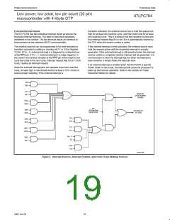
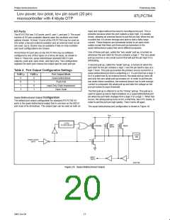
Quasi-Bidirectional Output Configuration
The default port output configuration for standard 87LPC764 I/O
ports is the quasi-bidirectional output that is common on the 80C51
and most of its derivatives. This output type can be used as both an
The quasi-bidirectional port configuration is shown in Figure 10.
V
DD
2 CPU
CLOCK DELAY
P
P
P
VERY
WEAK
STRONG
WEAK
PORT
PIN
PORT LATCH
DATA
N
INPUT
DATA
SU01159
Figure 10. Quasi-Bidirectional Output
17
2001 Oct 26

 NXP [ NXP ]