Philips Semiconductors
Preliminary data
Low power, low price, low pin count (20 pin)
microcontroller with 4 kbyte OTP
87LPC764
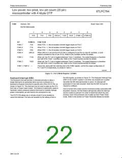
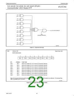
P2M1
Address: A4h
Reset Value: 00h
Not Bit Addressable
7
6
5
4
3
2
1
0
P2S
P1S
P0S
ENCLK T1OE
T0OE
(P2M1.1) (P2M1.0)
BIT
SYMBOL
FUNCTION
P2M1.7
P2M1.6
P2M1.5
P2M1.4
P2S
P1S
When P2S = 1, this bit enables Schmitt trigger inputs on Port 2.
When P1S = 1, this bit enables Schmitt trigger inputs on Port 1.
When P0S = 1, this bit enables Schmitt trigger inputs on Port 0.
P0S
ENCLK
When ENCLK is set and the 87LPC764 is configured to use the on-chip RC oscillator, a clock
output is enabled on the X2 pin (P2.0). Refer to the Oscillator section for details.
P2M1.3
T1OE
T0OE
—
When set, the P0.7 pin is toggled whenever Timer 1 overflows. The output frequency is therefore
one half of the Timer 1 overflow rate. Refer to the Timer/Counters section for details.
P2M1.2
When set, the P1.2 pin is toggled whenever Timer 0 overflows. The output frequency is therefore
one half of the Timer 0 overflow rate. Refer to the Timer/Counterssection for details.
P2M1.1, P2M1.0
These bits, along with the matching bits in the P2M2 register, control the output configuration of
P2.1 and P2.0 respectively, as shown in Table 4.
SU01597
Figure 13. Port 2 Mode Register 1 (P2M1)
the KBI register, as shown in Figure 15. The Keyboard Interrupt Flag
Keyboard Interrupt (KBI)
(KBF) in the AUXR1 register is set when any enabled pin is pulled
low while the KBI interrupt function is active. An interrupt will
generated if it has been enabled. Note that the KBF bit must be
cleared by software.
The Keyboard Interrupt function is intended primarily to allow a
single interrupt to be generated when any key is pressed on a
keyboard or keypad connected to specific pins of the 87LPC764, as
shown in Figure 14. This interrupt may be used to wake up the CPU
from Idle or Power Down modes. This feature is particularly useful in
handheld, battery powered systems that need to carefully manage
power consumption yet also need to be convenient to use.
Due to human time scales and the mechanical delay associated with
keyswitch closures, the KBI feature will typically allow the interrupt
service routine to poll port 0 in order to determine which key was
pressed, even if the processor has to wake up from Power Down
mode. Refer to the section on Power Reduction Modes for details.
The 87LPC764 allows any or all pins of port 0 to be enabled to
cause this interrupt. Port pins are enabled by the setting of bits in
19
2001 Oct 26

 NXP [ NXP ]