Philips Semiconductors
Preliminary data
Low power, low price, low pin count (20 pin)
microcontroller with 4 kbyte OTP
87LPC764
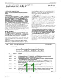
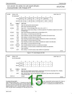
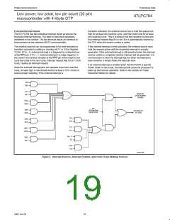
I2CON
Address: D8h
Reset Value: 81h
1
Bit Addressable
7
6
5
4
3
2
1
0
READ
RDAT
ATN
DRDY
ARL
STR
STP
MASTER
—
CXA
IDLE
CDR
CARL
CSTR
CSTP
XSTR
XSTP
WRITE
BIT
SYMBOL
RDAT
CXA
FUNCTION
I2CON.7
Read: the most recently received data bit.
Write: clears the transmit active flag.
“
I2CON.6
“
ATN
Read: ATN = 1 if any of the flags DRDY, ARL, STR, or STP = 1.
2
2
IDLE
Write: in the I C slave mode, writing a 1 to this bit causes the I C hardware to ignore the bus until it
is needed again.
I2CON.5
DRDY
CDR
Read: Data Ready flag, set when there is a rising edge on SCL.
Write: writing a 1 to this bit clears the DRDY flag.
“
I2CON.4
ARL
Read: Arbitration Loss flag, set when arbitration is lost while in the transmit mode.
Write: writing a 1 to this bit clears the CARL flag.
“
CARL
STR
I2CON.3
Read: Start flag, set when a start condition is detected at a master or non-idle slave.
Write: writing a 1 to this bit clears the STR flag.
“
CSTR
STP
I2CON.2
Read: Stop flag, set when a stop condition is detected at a master or non-idle slave.
Write: writing a 1 to this bit clears the STP flag.
“
CSTP
MASTER
XSTR
—
I2CON.1
Read: indicates whether this device is currently as bus master.
Write: writing a 1 to this bit causes a repeated start condition to be generated.
Read: undefined.
“
I2CON.0
“
XSTP
Write: writing a 1 to this bit causes a stop condition to be generated.
SU01155
2
Figure 6. I C Control Register (I2CON)
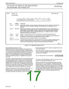
I2DAT
Address: D9h
Not Bit Addressable
Reset Value: xxh
7
6
5
4
3
2
1
0
READ
RDAT
—
—
—
—
—
—
—
XDAT
—
—
—
—
—
—
—
WRITE
BIT
SYMBOL
FUNCTION
I2DAT.7
RDAT
Read: the most recently received data bit, captured from SDA at every rising edge of SCL. Reading
I2DAT also clears DRDY and the Transmit Active state.
“
XDAT
–
Write: sets the data for the next transmitted bit. Writing I2DAT also clears DRDY and sets the
Transmit Active state.
I2DAT.6–0
Unused.
SU01156
2
Figure 7. I C Data Register (I2DAT)
Checking ATN and DRDY
STR, or STP is set, clearing DRDY will not release SCL to high, so
2
When a program detects ATN = 1, it should next check DRDY. If
DRDY = 1, then if it receives the last bit, it should capture the data
from RDAT (in I2DAT or I2CON). Next, if the next bit is to be sent, it
should be written to I2DAT. One way or another, it should clear
DRDY and then return to monitoring ATN. Note that if any of ARL,
that the I C will not go on to the next bit. If a program detects
ATN = 1, and DRDY = 0, it should go on to examine ARL, STR,
and STP.
12
2001 Oct 26

 NXP [ NXP ]