Philips Semiconductors
Preliminary specification
80C51 8-bit microcontroller
8K/256 OTP, 8 channel 10 bit A/D, I2C, PWM,
capture/compare, high I/O, low voltage (2.7V–5.5V), low power
P87C552
7
6
5
4
3
2
1
0
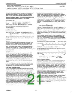
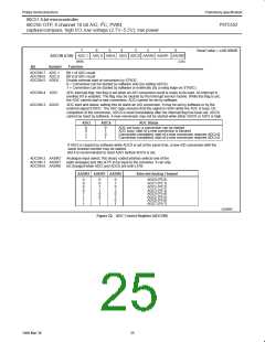
Reset Value = xx00 0000B
ADCON (C5H) ADC.1 ADC.0 ADEX ADCI ADCS AADR2 AADR1 AADR0
(MSB)
(LSB)
Bit
Symbol
Function
ADCON.7 ADC.1
ADCON.6 ADC.0
ADCON.5 ADEX
Bit 1 of ADC result
Bit 0 of ADC result
Enable external start of conversion by STADC
0 = Conversion can be started by software only (by setting ADCS)
1 = Conversion can be started by software or externally (by a rising edge on STADC)
ADCON.4 ADCI
ADCON.3 ADCS
ADC interrupt flag: this flag is set when an A/D conversion result is ready to be read. An interrupt is
invoked if it is enabled. The flag may be cleared by the interrupt service routine. While this flag is set,
the ADC cannot start a new conversion. ADCI cannot be set by software.
ADC start and status: setting this bit starts an A/D conversion. It may be set by software or by the
external signal STADC. The ADC logic ensures that this signal is HIGH while the ADC is busy. On
completion of the conversion, ADCS is reset immediately after the interrupt flag has been set. ADCS
cannot be reset by software. A new conversion may not be started while either ADCS or ADCI is high.
ADCI
ADCS
ADC Status
0
0
1
1
0
1
0
1
ADC not busy; a conversion can be started
ADC busy; start of a new conversion is blocked
Conversion completed; start of a new conversion requires ADCI=0
Conversion completed; start of a new conversion requires ADCI=0
If ADCI is cleared by software while ADCS is set at the same time, a new A/D conversion with the
same channel number may be started.
But it is recommended to reset ADCI before ADCS is set.
ADCON.2 AADR2
ADCON.1 AADR1
ADCON.0 AADR0
Analogue input select: this binary coded address selects one of the
eight analogue port bits of P5 to be input to the converter. It can only
be changed when ADCI and ADCS are both LOW.
AADR2 AADR1 AADR0
Selected Analog Channel
0
0
0
0
1
1
1
1
0
0
1
1
0
0
1
1
0
1
0
1
0
1
0
1
ADC0 (P5.0)
ADC1 (P5.1)
ADC2 (P5.2)
ADC3 (P5.3)
ADC4 (P5.4)
ADC5 (P5.5)
ADC6 (P5.6)
ADC7 (P5.7)
SU00960
Figure 22. ADC Control Register (ADCON)
25
1999 Mar 30

 NXP [ NXP ]