Philips Semiconductors
Preliminary specification
80C51 8-bit microcontroller
8K/256 OTP, 8 channel 10 bit A/D, I2C, PWM,
capture/compare, high I/O, low voltage (2.7V–5.5V), low power
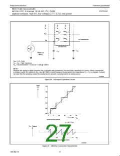
P87C552
+
–
V
V
in
DAC
SUCCESSIVE
APPROXIMATION
REGISTER
SUCCESSIVE
APPROXIMATION
CONTROL LOGIC
DAC
START
15/16
STOP
59/64
FULL SCALE
1
V
in
3/4
29/32
7/8
1/2
V
DAC
0
1
2
3
4
5
6
t/tau
SU00958
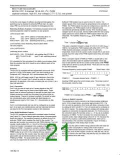
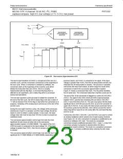
Figure 20. Successive Approximation ADC
The low-to-high transition of STADC is recognized at the end of a
machine cycle, and the conversion commences at the beginning of
the next cycle. When a conversion is initiated by software, the
conversion starts at the beginning of the machine cycle which
follows the instruction that sets ADCS. ADCS is actually
implemented with two flip-flops: a command flip-flop which is
affected by set operations, and a status flag which is accessed
during read operations.
previous result), and VDAC is compared to Vin again. If the input
voltage is greater than VDAC, then the bit being tested remains set;
otherwise the bit being tested is cleared. This process is repeated
until all ten bits have been tested, at which stage the result of the
conversion is held in the successive approximation register.
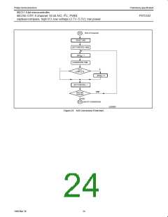
Figure 21 shows a conversion flow chart. The bit pointer identifies
the bit under test. The conversion takes four machine cycles per bit.
The end of the 10-bit conversion is flagged by control bit ADCON.4
(ADCI). The upper 8 bits of the result are held in special function
register ADCH, and the two remaining bits are held in ADCON.7
(ADC.1) and ADCON.6 (ADC.0). The user may ignore the two least
significant bits in ADCON and use the ADC as an 8-bit converter (8
upper bits in ADCH). In any event, the total actual conversion time is
50 machine cycles for the 8XC552. ADCI will be set and the ADCS
status flag will be reset 50 (or 24) cycles after the command flip-flop
(ADCS) is set.
The next two machine cycles are used to initiate the converter. At
the end of the first cycle, the ADCS status flag is set and a value of
“1” will be returned if the ADCS flag is read while the conversion is in
progress. Sampling of the analog input commences at the end of the
second cycle.
During the next eight machine cycles, the voltage at the previously
selected pin of port 5 is sampled, and this input voltage should be
stable in order to obtain a useful sample. In any event, the input
voltage slew rate must be less than 10V/ms in order to prevent an
undefined result.
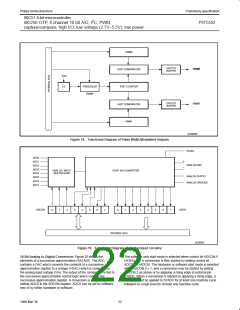
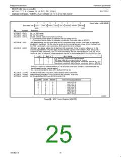
Control bits ADCON.0, ADCON.1, and ADCON.2 are used to control
an analog multiplexer which selects one of eight analog channels
(see Figure 22). An ADC conversion in progress is unaffected by an
external or software ADC start. The result of a completed
conversion remains unaffected provided ADCI = logic 1; a new ADC
conversion already in progress is aborted when the idle or
The successive approximation control logic first sets the most
significant bit and clears all other bits in the successive
approximation register (10 0000 0000B). The output of the DAC
(50% full scale) is compared to the input voltage Vin. If the input
voltage is greater than VDAC, then the bit remains set; otherwise it
is cleared.
power-down mode is entered. The result of a completed conversion
(ADCI = logic 1) remains unaffected when entering the idle mode.
The successive approximation control logic now sets the next most
significant bit (11 0000 0000B or 01 0000 0000B, depending on the
23
1999 Mar 30

 NXP [ NXP ]