Philips Semiconductors
Preliminary specification
80C51 8-bit microcontroller
8K/256 OTP, 8 channel 10 bit A/D, I2C, PWM,
capture/compare, high I/O, low voltage (2.7V–5.5V), low power
P87C552
Sm
Sm
Rm
Rm
N+1
N+1
I
N+1
N
N
TO COMPARATOR
I
N
+
MULTIPLEXER
R
S
C
C
C
S
V
ANALOG
INPUT
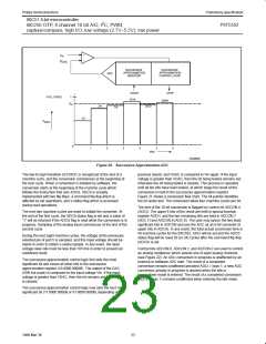
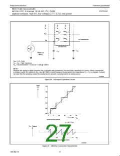
Rm = 0.5 - 3 kΩ
C
R
+ C = 15pF maximum
= Recommended < 9.6 kΩ for 1 LSB @ 12MHz
S
S
C
NOTE:
Because the analog to digital converter has a sampled-data comparator, the input looks capacitive to a source. When a conversion
is initiated, switch Sm closes for 8t (8µs @ 12MHz crystal frequency) during which time capacitance C + C is charged. It should
CY
S
C
be noted that the sampling causes the analog input to present a varying load to an analog source.
SU00962
Figure 24. A/D Input: Equivalent Circuit
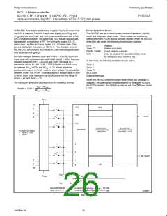
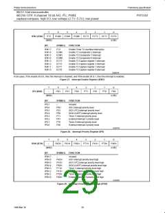
CODE
101
OUT
100
011
010
001
000
0
q
2q
3q
4q
5q
V
in
QUANTIZATION ERROR
q = LSB = 5 mV
V
– V
digital
in
+ q/2
– q/2
V
in
SYMMETRICAL QUANTIZATION ERROR
SU00963
Figure 25. Effective Conversion Characteristic
27
1999 Mar 30

 NXP [ NXP ]