Philips Semiconductors
Preliminary specification
80C51 8-bit microcontroller
8K/256 OTP, 8 channel 10 bit A/D, I2C, PWM,
capture/compare, high I/O, low voltage (2.7V–5.5V), low power
P87C552
Interrupts
interrupt enable special function registers IEN0 and IEN1. All
The 8XC552 has fifteen interrupt sources, each of which can be
assigned one of four priority levels. The five interrupt sources
common to the 80C51 are the external interrupts (INT0 and INT1),
the timer 0 and timer 1 interrupts (IT0 and IT1), and the serial I/O
interrupt (RI or TI). In the 8XC552, the standard serial interrupt is
called SIO0.
interrupt sources can also be globally enabled or disabled by setting
or clearing bit EA in IEN0. The interrupt enable registers are
described in Figures 26 and 27.
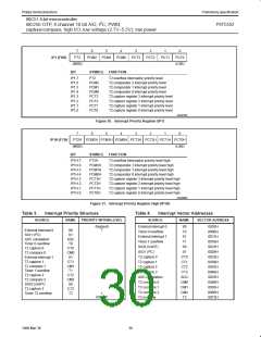
There are 3 SFRs associated with each of the four-level interrupts.
They are the IENx, IPx, and IPxH. (See Figures 28, 29, and 30.) The
IPxH (Interrupt Priority High) register makes the four-level interrupt
structure possible.
The eight Timer T2 interrupts are generated by flags CTI0-CT13,
CMI0-CMI2, and by the logical OR of flags T2OV and T2BO. Flags
CTI0 to CT13 are set by input signals CT0I to CT3i. Flags CMI0 to
CMI2 are set when a match occurs between Timer T2 and the
compare registers CM0, CM1, and CM2. When an 8-bit or 16-bit
overflow occurs, flags T2BO and T2OV are set, respectively. These
nine flags are not cleared by hardware and must be reset by
software to avoid recurring interrupts.
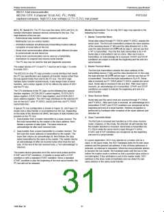
The function of the IPxH SFR is simple and when combined with the
IPx SFR determines the priority of each interrupt. The priority of
each interrupt is determined as shown in the following table:
PRIORITY BITS
INTERRUPT PRIORITY LEVEL
IPxH.x
IPx.x
0
0
1
1
0
1
0
1
Level 0 (lowest priority)
Level 1
The ADC interrupt is generated by the ADCI flag in the ADC control
register (ADCON). This flag is set when an ADC conversion result is
ready to be read. ADCI is not cleared by hardware and must be
reset by software to avoid recurring interrupts.
Level 2
Level 3 (highest priority)
2
The SIO1 (I C) interrupt is generated by the SI flag in the SIO1
control register (S1CON). This flag is set when S1STA is loaded
with a valid status code.
The priority scheme for servicing the interrupts is the same as that
for the 80C51, except there are four interrupt levels rather than two
as on the 80C51. An interrupt will be serviced as long as an interrupt
of equal or higher priority is not already being serviced. If an
interrupt of equal or higher level priority is being serviced, the new
interrupt will wait until it is finished before being serviced. If a lower
priority level interrupt is being serviced, it will be stopped and the
new interrupt serviced. When the new interrupt is finished, the lower
priority level interrupt that was stopped will be completed.
The ADCI flag may be reset by software. It cannot be set by
software. All other flags that generate interrupts may be set or
cleared by software, and the effect is the same as setting or
resetting the flags by hardware. Thus, interrupts may be generated
by software and pending interrupts can be canceled by software.
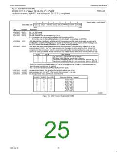
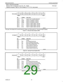
Interrupt Enable Registers: Each interrupt source can be
individually enabled or disabled by setting or clearing a bit in the
7
6
5
4
3
2
1
0
IEN0 (A8H)
EA
EAD
ES1
ES0
ET1
EX1
ET0
EX0
(LSB)
(MSB)
BIT
SYMBOL FUNCTION
IEN0.7
EA
Global enable/disable control
0 = No interrupt is enabled
1 = Any individually enabled interrupt will be accepted
IEN0.6
IEN0.5
IEN0.4
IEN0.3
IEN0.2
IEN0.1
IEN0.0
EAD
ES1
ES0
ET1
EX1
ET0
EX0
Eanble ADC interrupt
Enable SIO1 (I C) interrupt
Enable SIO0 (UART) interrupt
Enable Timer 1 interrupt
Enable External interrupt 1
Enable Timer 0 interrupt
2
Enable External interrupt 0
SU00762
Figure 26. Interrupt Enable Register (IEN0)
28
1999 Mar 30

 NXP [ NXP ]