Philips Semiconductors
Preliminary specification
80C51 8-bit microcontroller
8K/256 OTP, 8 channel 10 bit A/D, I2C, PWM,
capture/compare, high I/O, low voltage (2.7V–5.5V), low power
P87C552
Timer T3, The Watchdog Timer
In order to prepare software for watchdog operation, a programmer
should first determine how long his system can sustain an
erroneous processor state. The result will be the maximum
watchdog interval. As the maximum watchdog interval becomes
shorter, it becomes more difficult for the programmer to ensure that
the user program always reloads the watchdog timer within the
watchdog interval, and thus it becomes more difficult to implement
watchdog operation.
In addition to Timer T2 and the standard timers, a watchdog timer is
also incorporated on the 8xC552. The purpose of a watchdog timer
is to reset the microcontroller if it enters erroneous processor states
(possibly caused by electrical noise or RFI) within a reasonable
period of time. An analogy is the “dead man’s handle” in railway
locomotives. When enabled, the watchdog circuitry will generate a
system reset if the user program fails to reload the watchdog timer
within a specified length of time known as the “watchdog interval.”
The programmer must now partition the software in such a way that
reloading of the watchdog is carried out in accordance with the above
requirements. The programmer must determine the execution times
of all software modules. The effect of possible conditional branches,
subroutines, external and internal interrupts must all be taken into
account. Since it may be very difficult to evaluate the execution
times of some sections of code, the programmer should use worst
case estimations. In any event, the programmer must make sure
that the watchdog is not activated during normal operation.
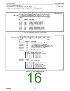
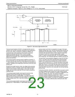
Watchdog Circuit Description: The watchdog timer (Timer T3)
consists of an 8-bit timer with an 11-bit prescaler as shown in
Figure 17. The prescaler is fed with a signal whose frequency is
1/12 the oscillator frequency (1MHz with a 12MHz oscillator). The
8-bit timer is incremented every “t” seconds, where:
t = 12 × 2048 × 1/f
OSC
(= 1.5ms at f
= 16MHz)
OSC
If the 8-bit timer overflows, a short internal reset pulse is generated
which will reset the 8xC552. A short output reset pulse is also
generated at the RST pin. This short output pulse (3 machine
cycles) may be destroyed if the RST pin is connected to a capacitor.
This would not, however, affect the internal reset operation.
The watchdog timer is reloaded in two stages in order to prevent
erroneous software from reloading the watchdog. First PCON.4
(WLE) must be set. The T3 may be loaded. When T3 is loaded,
PCON.4 (WLE) is automatically reset. T3 cannot be loaded if
PCON.4 (WLE) is reset. Reload code may be put in a subroutine as
it is called frequently. Since Timer T3 is an up-counter, a reload
value of 00H gives the maximum watchdog interval (510ms with a
12MHz oscillator), and a reload value of 0FFH gives the minimum
watchdog interval (2ms with a 12MHz oscillator).
Watchdog operation is activated when external pin EW is tied low.
When EW is tied low, it is impossible to disable the watchdog
operation by software.
How to Operate the Watchdog Timer: The watchdog timer has to
be reloaded within periods that are shorter than the programmed
watchdog interval; otherwise the watchdog timer will overflow and a
system reset will be generated. The user program must therefore
continually execute sections of code which reload the watchdog
timer. The period of time elapsed between execution of these
sections of code must never exceed the watchdog interval. When
using a 16MHz oscillator, the watchdog interval is programmable
between 1.5ms and 392ms.
In the idle mode, the watchdog circuitry remains active. When
watchdog operation is implemented, the power-down mode cannot
be used since both states are contradictory. Thus, when watchdog
operation is enabled by tying external pin EW low, it is impossible to
enter the power-down mode, and an attempt to set the power-down
bit (PCON.1) will have no effect. PCON.1 will remain at logic 0.
INTERNAL BUS
V
DD
P
OVERFLOW
f
/12
OSC
PRESCALER (11-BIT)
CLEAR
TIMER T3 (8-BIT)
LOAD LOADEN
RST
INTERNAL
RESET
WRITE T3
R
RST
CLEAR
WLE
PD
LOADEN
PCON.1
PCON.4
EW
INTERNAL BUS
SU00955
Figure 17. Watchdog Timer
20
1999 Mar 30

 NXP [ NXP ]