Philips Semiconductors
PCA82C250 / 251 CAN Transceiver
Application Note
AN96116
5.3
Examples
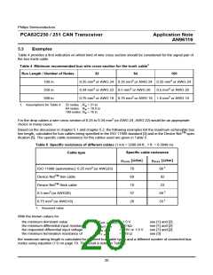
Table 4 provides a first indication on which kind of wire cross section should be considered for the signal pair of
the bus trunk cable.
1
Table 4 Minimum recommended bus wire cross-section for the trunk cable
Bus Length / Number of Nodes
32
64
100
2
2
2
100 m
250 m
500 m
0.25 mm or AWG 24 0.25 mm or AWG 24 0.25 mm or AWG 24
2
2
2
0.34 mm or AWG 22 0.5 mm or AWG 20
0.5 mm or AWG 20
2
2
2
0.75 mm or AWG 18 0.75 mm or AWG 18 1.0 mm or AWG 18
1. Assumptions for Table 4: 32 nodes : R < 21 Ω
w
64 nodes : R < 18.5 Ω
w
100 nodes: R < 16 Ω
w
2
For the drop cables a wire cross section of 0.25 to 0.34 mm (or AWG 24, AWG 22) would be an appropriate
choice in many cases.
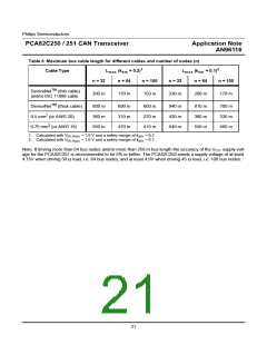
Based on the discussion in chapter 5.1 and chapter 5.2, the following examples list the maximum achievable bus
TM
line length, calculated for bus cables being specified in the ISO 11898 standard [3] and in the Device Net spec-
ification [5]. The specific cable resistance for the cables used are given in Table 5.
Table 5 Specific resistance of different cables (1 km = 3280.84 ft., 1 ft. = 0.3048 m)
Specific cable resistance
Cable type
ρ
[Ω/km]
ρ
[Ω/km]
max
nom
2
1
ISO 11898 (automotive): 0.25 mm (or AWG23)
70
90
TM
Device Net thin cable
69
18
37
26
92
23
TM
Device Net thick cable
2
1
0.5 mm (or AWG20)
50
2
1
0.75 mm (or AWG18)
33
1. Assumed value
With the known values for
the minimum dominant value
: V
: R
: V
: R
= 1.5 V
= 20 kΩ
= 0.9V or 1.0 V
= 118 Ω
see [1] and [2]
see [1] and [2]
see [1] and [2]
see [3]
diff.out.min
diff.min
th.max
the minimum differential input resistance
the requested differential input voltage
the minimum termination resistance of
T.min
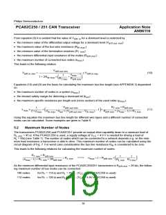
the maximum wiring length is calculated for different bus cable types and a different number of connected bus
nodes using equation (11) on page 19. The result is listed in Table 6.
20

 NXP [ NXP ]