Philips Semiconductors
PCA82C250 / 251 CAN Transceiver
Application Note
AN96116
4.2
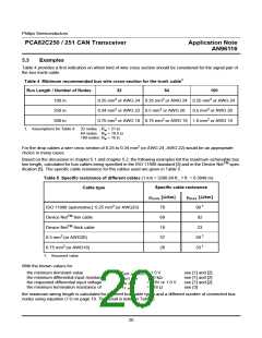
Bus Length in Slope Control Mode
In slope control mode the bus output slew rate is decreased intentionally, which implies an increase of the bus
node loop delay. Due to the CAN bit timing requirements, this is equivalent to a reduction of the maximum bus
line length at a given bit rate or reduction of the bit rate at a given bus length in a system compared to using the
high-speed mode.
The maximum achievable bus line length is given by (see also [4]):
t
prop
----------- – t
– t
loop.eff.oth
loop.eff
2
L
= -------------------------------------------------------------------------
(5)
max
t
p
With L
: Maximum achievable bus line length
max
t
t
t
t
: Maximum available two-way propagation delay (CAN bit timing)
prop
: Effective transceiver loop delay
loop.eff
loop.eff.oth
p
: Effective loop delay of other components e.g. CAN controller and optocouplers
: Specific bus line delay
From equation (5) it is obvious, that the maximum bus line length will increase, if the transceiver loop delay is
decreased. The loop delay of a transceiver, which is set to the high-speed mode, is smaller than the loop delay of
a transceiver, which is set to the slope control mode. Thus a higher bus line length can be achieved, if the trans-
ceiver is used in the high-speed mode, as a greater portion of the available propagation delay can be used for tol-
erating line delay.
This increase is given by the following equation:
t
(slope control mode)– t
(high speed mode)
∆ t
loop.eff
loop.eff
loop.eff
∆L
= ---------------------------------------------------------------------------------------------------------------------------------------------- = ----------------------
(6)
max
t
t
p
p
In a CAN network the effective maximum delay of a transceiver (also valid for the delay of other devices) are cal-
culated using the following equation
(See APPENDIX 1 for an explanation of used symbols and abbreviations):
t
= max{0.5 × (t
+ t
), t }
(7)
loop.eff.max
onRxD
offRxD
onRxD
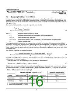
Table 2 gives an indication of the difference between using high-speed mode and slope control mode - in terms
of maximum bus length. The values below refer to a specific propagation delay of t = 5 ns/m on the bus cable.
p
Table 2 Difference of maximum bus length
o
Effective loop delay (upper limit at 125 C)
Difference between both
1
modes in terms of bus length
2
Product
slope-control mode
520 ns
high-speed mode
155 ns
∆ t
∆ L
loop.eff
max
PCA82C250
PCA82C251
365 ns
395 ns
~ 75 m
~ 80 m
550 ns
155 ns
1. At 5 ns/m specific propagation delay on the bus cable
2. Slope-control resistance R = 47 kΩ
ext
16

 NXP [ NXP ]