Philips Semiconductors
PCA82C250 / 251 CAN Transceiver
Application Note
AN96116
6. BUS TERMINATION AND TOPOLOGY ASPECTS
Generally the CAN high-speed standard ISO 11898 provides a single line structure as network topology. The bus
line is terminated at both ends with a single termination resistor. However in practice some deviation from that
topology may be needed to accommodate appropriate drop cable length of e.g. a few meters. Also a modified
termination network may be desirable in some applications e.g. for EMC related considerations. In this chapter
some modified bus termination concepts as well as topology aspects shall be discussed.
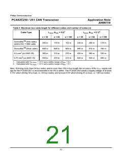
6.1
Split Termination Concept
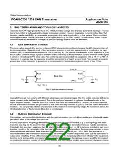
This is an option intended to provide enhanced EMC characteristics without changing the DC characteristics of
the terminated line. Basically each of the termination resistors is split into two resistors of equal value, i.e. two
resistors of 62 Ω instead of one resistor of 124 Ω (see Fig. 8). The special characteristic of this approach is, that
the so-called common-mode signal is available at the centre tap of the termination. As the common-mode signal
is simply a DC voltage in the ideal case, this centre tap can be grounded via a capacitor of e.g. 10 nF to 100 nF.
However it is obvious, that the capacitor should be connected to a “quiet” ground level. For example a separate
ground lead to the connector´s ground pin is recommended, if termination is placed inside of bus nodes.
CAN_H
R /2
R /2
T
T
Bus line
R /2
R /2
T
T
C
C
G
G
CAN_L
R /2 = 62 Ω
T
Fig. 8 Split termination concept
Basically there are two options with different advantages and disadvantages. The first option includes both termi-
nation resistors to be split and grounded. This is the preferred approach to optimize the characteristic in the
higher frequency range. However there is a chance that there are unwanted loop currents via ground potential,
as both termination resistors are grounded. In that case one may consider to ground only one of the termination
resistors. This can provide a better characteristic in the medium to low frequency range. As mentioned above, the
DC characteristics of the terminated bus line is not changed.
6.2
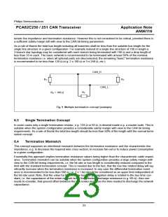
Multiple Termination Concept
This concept can be used in combination with the split termination concept above and targets at network topolo-
gies which differ from a single line structure.
In some applications a topology different from a single line structure is needed, e.g. a star topology with three
branches (see Fig. 9). To accommodate such a topology, the multiple termination concept may be considered.
Essentially this approach suggests, that the total termination resistance, i.e. 62 Ω, is being distributed over more
than two resistors. If for example a star topology is needed with three branches, then one may consider to termi-
nate each branch with about three times the total termination resistance, i.e. 180 Ω. With this approach it is
essential that the total termination resistance (i.e. all termination resistors in parallel) does suit the transceiver´s
output drive capability. If one of the branches is optional, e.g. for temporary attachment of diagnostic equipment,
then the trunk line would be terminated via two resistors of 180 Ω and the optional branch would be terminated
via another termination resistor of 180 Ω. It is obvious that this concept implies some mismatch between charac-
22

 NXP [ NXP ]