Philips Semiconductors
PCA82C250 / 251 CAN Transceiver
Application Note
AN96116
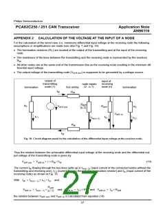
6.5
Unterminated Cable Drop Length
Initially the topology of a CAN bus system is considered to be close to a single line structure. However in a
number of cases some deviation from this topology may be needed, e.g. for temporary attachment of diagnostic
equipment to the bus line. Also bus nodes will often be connected to the bus line via an unterminated drop cable.
When unterminated drop cables are connected, some reflection effects will occur on the bus line. Reflection is
not necessarily a problem, as the network will provide some robustness thanks to e.g. receiver hysteresis and the
synchronization rules of the CAN protocol. Reflected waves are assumed to disappear once they arrive at one of
the bus line ends being terminated with the characteristic cable impedance. Essentially it depends on the bit tim-
ing parameters, the trunk cable length and the drop cable length whether reflections will be tolerated.
Basically it is advisable to specify an upper limit for the drop length and an upper limit for the so-called cumulative
drop length. The cumulative drop length is the sum of all drop cable length. As a rule of thumb, the following rela-
tion can be considered for the cable drop length:
t
PROPSEG
L < ---------------------------
(12)
u
50 × t
p
With t
being the length of the propagation segment of the bit period i.e. the length of time segment 1
PROPSEG
(TSEG1) minus the length of the resynchronization jump width (SJW), t being the specific line delay per length
p
unit (e.g. 5 ns/m) and L representing the length of the unterminated cable stub.
u
As to the cumulative drop length the following relation can be considered as a rule of thumb:
n
t
PROPSEG
---------------------------
L
<
ui
(13)
∑
10 × t
p
i = 1
In addition to that, the actual propagation delay on the bus line should be calculated on the basis of the total line
length i.e. trunk cable plus all drop cable length. This effectively leads to a reduction of the maximum trunk cable
length by the sum of the actual cumulative drop cable length at a given bit rate. If the above recommendations
are met, then the probability of reflection problems is considered to be fairly low.
Example:
Bit Rate = 500 kbit/s , t
= 12 × 125 ns = 1500 ns , t = 5 ns/m
p
PROPSEG
t
1500ns
PROPSEG
L < --------------------------- =
= 6 m
------------------------
ns
u
50 × t
p
50 × 5 ------
m
n
t
1500ns
ns
10 × 5 ------
m
PROPSEG
---------------------------
L
<
ui
= ------------------------ = 30 m
∑
10 × t
p
i = 1
As a rule of thumb an unterminated drop cable should be shorter than 6 m and the cumulative drop length should
be less than 30 m for a CAN propagation segment (PROP_SEG) length of 1500 ns.
24

 NXP [ NXP ]