Philips Semiconductors
PCA82C250 / 251 CAN Transceiver
Application Note
AN96116
teristic line impedance and termination resistance. However this is not considered to be critical, provided there is
a sufficient safety margin left with view to the CAN bit timing parameters.
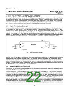
As a rule of thumb the total bus length including all branches shall be less than the suitable bus length for the
single line structure in a given configuration. For example instead of a single line structure of 100 m length a
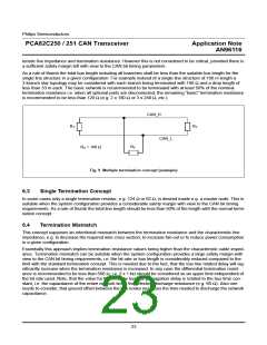
3-branch star topology may be considered with each branch being terminated with 180 Ω and a drop length of
less than 33 m each. The basic network is recommended to be terminated with at least 50% of the nominal
termination resistance i.e. when all optional parts are disconnected, the remaining “basic” termination resistance
is recommended to be less than 120 Ω (e.g. 2 x 180 Ω or 3 x 240 Ω, etc.).
CAN_H
R
R
T
T
CAN_L
R
R = 180 Ω
T
T
Fig. 9 Multiple termination concept (example)
6.3
Single Termination Concept
In some cases only a single termination resistor, e.g. 124 Ω or 62 Ω, is desired inside e.g. a master node. This is
suitable when the system configuration provides a considerable safety margin with view to the CAN bit timing
requirements. As a rule of thumb the total line length should be less than 50% of the length with the normal termi-
nation concept.
6.4
Termination Mismatch
This concept supposes an intentional mismatch between the termination resistance and the characteristic line
impedance, e.g. to decrease the required wire cross section, to increase fan-out or to reduce power consumption
in a given configuration.
Essentially this approach implies termination resistance values being higher than the characteristic cable imped-
ance. Termination mismatch can be suitable when the system configuration provides a large safety margin with
view to the CAN bit timing requirements, i.e. the bit rate or bus length is considerably reduced compared to the
limit with the standard termination concept. This is needed due to the fact, that the bus line related delay will sig-
nificantly increase when the termination resistance is increased. In any case the differential termination resist-
ance is recommended to be less than 500 Ω, i.e. 2 x 1 kΩ should be considered as an upper limit independent of
the bit rate used. Note, that the value for the two-way bus line propagation delay is related to the bus time con-
stant, i.e. the capacitance of the entire network times the effective discharge resistance (e.g. 60 Ω). Also one
needs to consider, that ground offset between the bus nodes increases the time needed to discharge the network
capacitance.
23

 NXP [ NXP ]