Philips Semiconductors
PCA82C250 / 251 CAN Transceiver
Application Note
AN96116
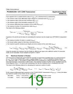
From equation (8) it is evident that the value of V
for a dominant level is restricted by
diff.in
• the minimum value of the differential output voltage for a dominant level (V
)
diff.out.min
• the maximum value of the bus wire resistance (R
)
W.max
• the minimum value of the termination resistors (R
)
T.min
• the minimum differential input resistance of the nodes (R
)
diff.min
• the maximum number of connected bus nodes (n
).
max
This leads to the following relation
V
diff.out.min
V
= -------------------------------------------------------------------------------------------- ≥ V
(10)
diff.in.min
diff.in.req
n
– 1
1
max
1 + 2R
×
+
----------------- ----------------------
W.max
R
R
diff.min
T.min
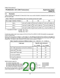
Equations (10) and (9) are the basis for calculating the maximum bus line length (see APPENDIX 3) dependent
on
• the maximum number of nodes in a system (n
)
max
• the desired safety margin for detecting a dominant bit (k
)
sm
• the maximum specific resistance per length unit (cross section) of the used cable (ρ
).
max
R
× R
V
1
2 × ρ
T.min
diff.min
diff.out.min
----------------------
-------------------------------------------------------------------------------
L
≤
× --------------------------------------------------------------------------------------------------------- – 1 ×
(11)
max
R
+ (n
– 1) × R
max T.min
V
+ k × (V
– V
)
th.max
max
diff.min
th.max
sm
diff.out.min
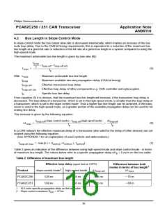
Using this equation the maximum bus line length for different wire types and a different number of connected
nodes can be calculated. Some examples are given in Table 6.
5.2
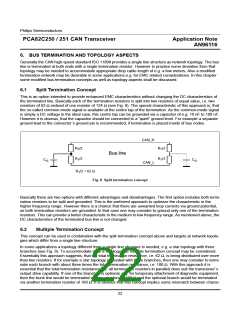
Maximum Number of Nodes
The transceivers PCA82C250 and PCA82C251 provide an output drive capability down to a minimum load of
= 45 Ω. If the PCA82C250 is used, a supply voltage of V > 4.9 V is needed for driving a load of
R
L.min
CC
R = 45Ω (see Table 1). The number of nodes which can be connected to a network depends e.g. on the mini-
L
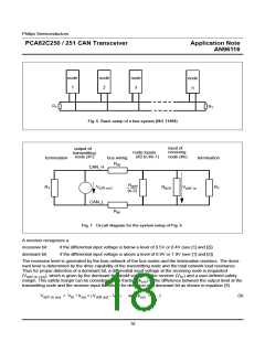
mum load resistance a transceiver is able to drive. This maximum number of nodes can be calculated using the
circuit diagram of Fig. 7. For worst case consideration the bus line resistance R is considered to be zero.
W
This leads to the following relations for calculating the maximum number of nodes:
R
× R
diff.min
1
2
T . min
----------------------------------------------------------------------------------- > R
===>
n
< 1 + R ×
diff.min
–
---------------- -----------------
L . min
max
(n
– 1) × R
+ 2R
T.min diff.min
R
R
max
L.min
T . min
As the minimum differential input resistance of the PCA82C250/251 transceivers is R
ing maximum number of bus nodes can be connected:
= 20 kΩ, the follow-
diff.min
106 nodes
112 nodes
for R = 118 Ω and R = 45 Ω ; (V
> 4.9V if 82C250 is used)
> 4.9V if 82C250 is used)
T
L
CC
CC
for R = 120 Ω and R = 45 Ω ; (V
T
L
19

 NXP [ NXP ]