Philips Semiconductors
PCA82C250 / 251 CAN Transceiver
Application Note
AN96116
4. SLOPE CONTROL FUNCTION
4.1
Slew Rate Calculation
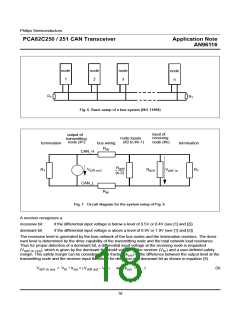
As mentioned above, the slew rate (SR) of the bus output signal is proportional to the current flow (I ) out of the
Rs
pin Rs. As the current is primarily determined by the slope-control resistance value R , a certain slew rate is
ext
achieved by applying a respective resistance. Note that there is a difference between the single-ended slew rate,
which applies to each bus voltage individually and the differential signal slew rate, which applies to the differential
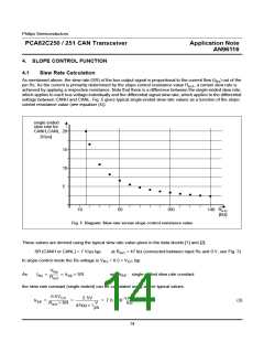
voltage between CANH and CANL. Fig. 5 gives typical single-ended slew rate values as a function of the slope-
control resistance value (see equation (4)).
single ended
slew rate for
20
15
10
5
CANH,CANL
[V/µs]
10
50
100
R
140
ext
[kΩ]
Fig. 5 Diagram: Slew rate versus slope control resistance value
These values are derived using the typical slew rate value given in the data sheets [1] and [2]:
SR (CANH or CANL) = 7 V/µs typ. at R = 47 kΩ (connected between input Rs and 0 V, see Fig. 3)
ext
In slope-control mode the Rs-voltage is V = 0.5 × V
typ.
CC
Rs
V
Rs
As
I
= ----------- = k × SR
with k : single-ended slew rate constant
SE
Rs
SE
R
ext
the slew rate constant (single-ended) can be calculated using above typical values.
0.5V
µ s
-------
k Ω
2.5V
CC
– 3
k
= -------------------------- = ------------------------------- = 7 . 6 × 1 0
(3)
SE
R
× SR
V
ext
------
µs
47kΩ × 7
14

 NXP [ NXP ]