Philips Semiconductors
PCA82C250 / 251 CAN Transceiver
Application Note
AN96116
3. OPERATION MODES
The PCA82C250 and PCA82C251 provide three different operation modes. Mode control is being provided
through the Rs control input.
The first mode is the high-speed mode supporting maximum bus speed and/or length.
The second mode is the so-called slope control mode which should be considered if unshielded bus wires shall
be used. In this mode the output slew rate can be decreased intentionally, e.g. to reduce electromagnetic emis-
sion.
The third mode is the stand-by mode being of interest especially in battery powered applications, when the sys-
tem power consumption needs to be very low. System reactivation is performed through transmission of a mes-
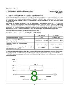
sage. Fig. 3 gives an example for switching the transceiver between stand-by mode and normal operating mode.
• Px,y = HIGH:
• Px,y = LOW:
the PCA82C250/251 is switched to stand-by mode (V > 0.75 × V
)
Rs
CC
the PCA82C250/251 is switched to normal operating mode, which is either high-speed mode
or slope control mode, depending essentially upon the resistance connected to Rs.
Usually the following resistance values for the slope-control resistor R
are suitable:
ext
• 0 Ω < R
< 1.8 kΩ
high-speed mode (V < 0.3 × V
)
CC
ext
Rs
• 16.5 kΩ < R
< 140 kΩ
slope control mode (10 µA < - I < 200 µA)
Rs
ext
In the following these three operation modes shall be discussed in more detail.
3.1
High-Speed Mode
This mode is suitable to achieve a maximum bit rate and/or bus length. The high-speed mode is commonly
TM
employed in general industrial applications such as the CAN based system DeviceNet . In this mode the bus
output signals are switched as fast as possible and therefore a shielded bus cable usually would be appropriate
to prevent a possible disturbance of e.g. a car radio by the bus signal.
The high-speed mode is selected with V < 0.3 × V . This can be achieved with a direct connection of the Rs
Rs
CC
control input to an output port of a microcontroller or ground potential or an active-high reset signal (see Fig. 3
and Fig. 4).
In high-speed mode the transceivers provide an effective loop delay of as low as 145 ns max. (155 ns for
T
> 85°C). With view to the CAN bit timing requirements, the effective loop delay is the maximum of the dom-
amb
inant edge loop delay and the average value of dominant and recessive edge loop delay.
t
= max{0.5 × (t + t ), t
}
onRxD
loop.eff
onRxD
offRxD
3.2
Slope Control Mode
In several applications the use of an unshielded bus cable will be desirable e.g. for system cost reasons. How-
ever using an unshielded cable implies additional requirements to be met by the transceiver product e.g. with
view to electromagnetic compatibility (EMC). Using the PCA82C250/251 the slew rate of the bus signal can be
decreased intentionally, which is recommended if an unshielded bus cable shall be used. The slew rate can be
set via a series resistance value R
being connected to the control pin Rs. With respect to the CAN bit timing
ext
requirements a decreased slew rate implies an increase of the bus node loop delay and thus a lower bus length
at a given bit rate or alternatively a lower bit rate at a given bus length. In slope control mode the bus output slew
rate is basically proportional to the current flow out of pin Rs in the range of 10 µA < - I < 200 µA (see data
Rs
sheets [1], [2]). If the Rs output current is in that range, then a voltage of approximately 0.5 × V
will be output
CC
at the pin Rs. The transceiver is set to slope control mode when an appropriate resistance value is applied
between the Rs pin and ground potential. As a rule of thumb the resistance value should be in the range of
16.5 kΩ < R
< 140 kΩ to meet the above-mentioned range for the Rs output current.
ext
12

 NXP [ NXP ]