Philips Semiconductors
PCA82C250 / 251 CAN Transceiver
Application Note
AN96116
e.g. PCx82C200
CAN - Contoller
CTX0 CTX1
/ TX0 / TX1
CRX0 CRX1
/ RX0 / RX1
6.2k
360
4.3k
360
6N137
100n
100n
+5V
+5V
0V
Isolation
6N137
+5V
360
either connection to
360
0V
high-active reset signal
R
ext
+5V
n.c.
VREF
TxD
RxD
Rs
V
RST
+5V
PCA 82C250/251
CAN Transceiver
CC
100n
5V
Regulator
0V
GND
CANH CANL
or connection to ground
JK512152.GWM
ISO 11898 Standard
CAN_H
CAN_L
124
CAN Bus Line
124
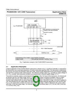
Programming of the Output Control Register (example)
Output Control TX0 push-pull, dominant = low e.g. 1A
hex
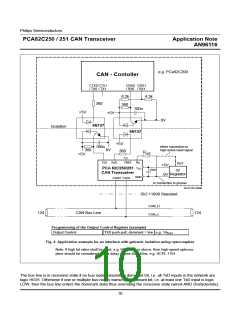
Fig. 4 Application example for an interface with galvanic isolation using optocouplers
Note: If high bit rates shall be used, e.g. 500 kbit/s or above, then high-speed optocou-
plers should be considered with a delay of less than 40ns, e.g. HCPL-7101.
The bus line is in recessive state if no bus node transmits a dominant bit, i.e. all TxD inputs in the network are
logic HIGH. Otherwise if one or multiple bus nodes transmit a dominant bit, i.e. at least one TxD input is logic
LOW, then the bus line enters the dominant state thus overriding the recessive state (wired-AND characteristic).
10

 NXP [ NXP ]