Philips Semiconductors
PCA82C250 / 251 CAN Transceiver
Application Note
AN96116
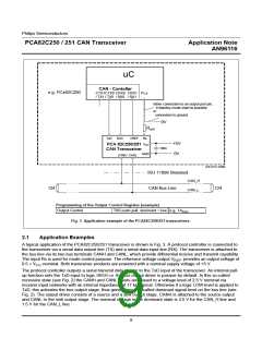
The receiver comparator converts the differential bus signal to a logic level signal which is output at RxD. The
serial receive data stream is provided to the bus protocol controller for decoding. The receiver comparator is
always active i.e. it monitors the bus while the bus node is transmitting a message. This is required e.g. for safety
reasons and to support the non-destructive bit by bit contention scheme of CAN. Some controller products pro-
vide an analog receive interface (RX0, RX1). In that case RX0 usually needs to be connected to the RxD output
and RX1 needs to be biased to an appropriate voltage level. This can be done e.g. by using the V
Fig. 3) or by using a resistive voltage divider (see Fig. 4).
output (see
REF
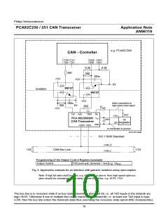
In Fig. 3 the transceiver is directly connected to the protocol controller and its application circuitry. In cases where
galvanic isolation is desired, optocouplers can be placed e.g. between the transceiver and the protocol controller
as shown in Fig. 4. When using optocouplers one has to pay attention to choose the right default state when the
circuitry at the protocol controller side of the isolation is not powered. In such a case the optocoupler being
attached to TxD will be “dark” i.e. LED switched off. When this optocoupler is off/dark, then a logic HIGH-level
has to be output to the TxD input of the transceiver for fail-safe purpose. Also if using optocouplers one may con-
sider to attach the Rs mode control input to an active-high reset signal, e.g. to disable the transceiver when the
local transceiver supply voltage is not OK e.g. during ramp-up and -down.
However using optocouplers generally increases the so-called loop delay of a bus node, if placed between the
transceiver and the protocol controller. The signal has to pass these devices twice per node, i.e. transmit and
receive path, which effectively decreases the maximum achievable bus length at a given bit rate. This fact has to
be considered when calculating the maximum achievable bus length due to propagation delays in a CAN net-
work. For more details please refer e.g. to [4].
2.2
Reference Voltage Output
The PCA82C250/251 provides a reference voltage output V
, which may be used e.g. to bias one of the
REF
inputs of a CAN protocol controller´s differential input comparator as shown in Fig. 3. In other cases a reference
voltage may be generated locally at the protocol controller input as shown e.g. in Fig. 4. Which solution is appro-
priate in a system depends on the application and the bus input structure of the protocol controller product.
11

 NXP [ NXP ]