Philips Semiconductors
PCA82C250 / 251 CAN Transceiver
Application Note
AN96116
2. APPLICATION OF THE PCA82C250 AND PCA82C251
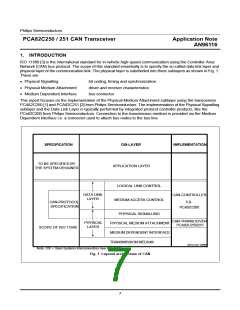
The PCA82C250/251 transceiver products basically provide interfacing between a protocol controller and a phys-
ical transmission line. They are designed to transmit data with a bit rate of up to 1 Mbit/s over a two-wire differen-
tial voltage bus line as described in the ISO 11898 standard. Their general features are listed in the data sheets
(see [1] and [2]).
Both devices are designed for the use in CAN bus systems with a nominal supply voltage of 12 V (PCA82C250)
and 24 V (PCA82C251) respectively. They are functionally identical and can be used in automotive and general
TM
industrial applications according to the relevant standards e.g. the ISO 11898 standard [3] and the DeviceNet
Specification [5]. Both the PCA82C250 and the PCA82C251 can communicate to one another in one network.
Moreover they are pin- & function-compatible i.e. they can be used with identical printed circuit boards.
Some main differences between both products are listed in Table 1.
Table 1 Main differences between PCA82C250 and PCA82C251
PCA82C250
PCA82C251
Nominal system supply voltage
12 V
12V and/or 24 V
Maximum bus terminal DC voltage
−8 V < V
< +18 V −40 V < V
< +40 V
CANL,H
CANL,H
(0 V < V
< 5.5 V)
CC
Maximum transient bus terminal voltage
(ISO 7637)
−150 V < V < +100 V
−200 V < V < +200 V
tr
tr
Minimum transceiver supply voltage for extended fan
V
> 4.9 V
V
> 4.5 V
CC
CC
out applications (R = 45 Ω)
L
For general industrial applications the PCA82C251 is recommended to be employed as to e.g. its higher break-
down voltage and its capability to drive loads down to 45 Ω over the whole supply voltage range. Also the
PCA82C251 draws less supply current in the recessive state and provides an enhanced bus output behaviour in
power-fail situations.
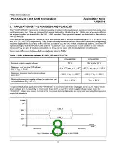
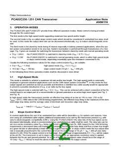
Voltage
5V
CAN_H
3.5V
2.5V
CAN_L
1.5V
EI203030
0V
Time
Recessive
Dominant
Recessive
Fig. 2 Nominal bus levels according to ISO 11898
8

 NXP [ NXP ]