ISP1160
Embedded USB Host Controller
Philips Semiconductors
µP bus I/F
[
]
[
]
D 15:0
D 15:0
RD_N
WR_N
CS_N
A1
RD_N
WR_N
CS_N
A0
MICRO-
PROCESSOR
ISP1160
INT
IRQ1
004aaa061
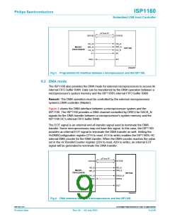
Fig 3. Programmed I/O interface between a microprocessor and the ISP1160.
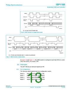
8.2 DMA mode
The ISP1160 also provides the DMA mode for external microprocessors to access its
internal FIFO buffer RAM. Data can be transferred by the DMA operation between a
microprocessor’s system memory and the ISP1160’s internal FIFO buffer RAM.
Remark: The DMA operation must be controlled by the external microprocessor
system’s DMA controller (Master).
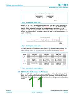
Figure 4 shows the DMA interface between a microprocessor system and the
ISP1160. The ISP1160 provides a DMA channel controlled by DREQ for DACK_N
signals for the DMA transfer between a microprocessor’s system memory and the
ISP1160 HC’s internal FIFO buffer RAM.
The EOT signal is an external end-of-transfer signal used to terminate the DMA
transfer. Some microprocessors may not have this signal. In this case, the ISP1160
provides an internal EOT signal to terminate the DMA transfer as well. Setting the
HcDMAConfiguration register (21H to read, A1H to write) enables the ISP1160’s HC
internal DMA counter for the DMA transfer. When the DMA counter reaches the value
set in the HcTransferCounter register (22H to read, A2H to write), an internal EOT
signal will be generated to terminate the DMA transfer.
µP bus I/F
[
]
[
]
D 15:0
D 15:0
RD_N
WR_N
RD_N
WR_N
MICRO-
PROCESSOR
ISP1160
DACK1_N
DREQ1
DACK_N
DREQ
EOT
EOT
004aaa062
Fig 4. DMA interface between a microprocessor and the ISP1160.
9397 750 11371
© Koninklijke Philips Electronics N.V. 2003. All rights reserved.
Product data
Rev. 04 — 04 July 2003
9 of 88

 NXP [ NXP ]