ISP1160
Embedded USB Host Controller
Philips Semiconductors
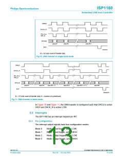
DREQ
DACK_N
RD_N or
WR_N
[
]
D 15:0
data #1
data #2
data #N
EOT
004aaa368
N = 1/2 byte count of transfer data.
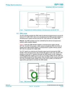
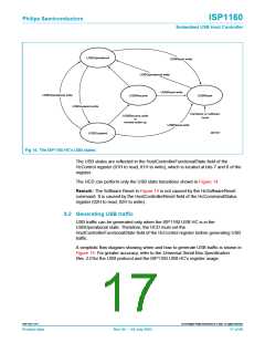
Fig 10. DMA transfer in single-cycle mode.
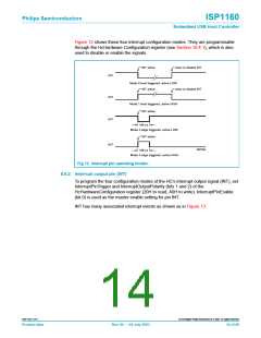
DREQ
DACK_N
RD_N or
WR_N
[
]
D 15:0
data #1
data #K
data #(K+1)
data #2K
data #(N−K+1)
data #N
EOT
004aaa369
N = 1/2 byte count of transfer data, K = number of cycles/burst.
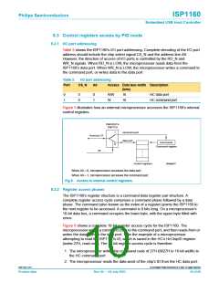
Fig 11. DMA transfer in burst mode.
In Figure 10 and Figure 11, the DMA transfer is configured such that DREQ is active
HIGH and DACK_N is active LOW.
8.6 Interrupts
The ISP1160 has an interrupt request pin INT.
8.6.1 Pin configuration
The interrupt output signals have four configuration modes:
Mode 0
Mode 1
Mode 2
Mode 3
Mode 0 level trigger, active LOW
Mode 1 level trigger, active HIGH
Mode 2 edge trigger, active LOW
Mode 3 edge trigger, active HIGH.
9397 750 11371
© Koninklijke Philips Electronics N.V. 2003. All rights reserved.
Product data
Rev. 04 — 04 July 2003
13 of 88

 NXP [ NXP ]