ISP1160
Embedded USB Host Controller
Philips Semiconductors
command port
data port
1
0
Host bus I/F
Control registers
Commands
Command register
A0
TransferCounter
22H/A2H
24H/A4H
EOT
2
1
0
µPInterrupt
=
internal EOT
2CH
40H/C0H
41H/C1H
BufferStatus
ITLBufferPort
ATLBufferPort
(16-bit width)
toggle
T
SOF
BufferStatus
Pointer
000H
001H
000H
001H
000H
001H
automatically
increments by 2
3FFH
3FFH
7FFH
ITL0 buffer RAM
(8-bit width)
ITL1 buffer RAM
(8-bit width)
ATL buffer RAM
(8-bit width)
MGT951
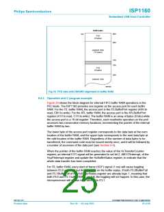
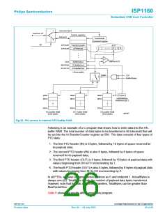
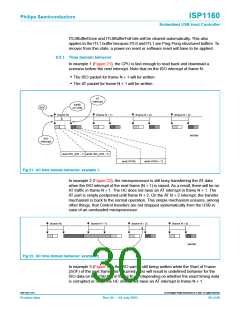
Fig 20. PIO access to internal FIFO buffer RAM.
Following is an example of a C program that shows how to write data into the ATL
buffer RAM. The total number of data bytes to be transferred is 80 (decimal) that will
be set into the HcTransferCounter register as 50H. The data consists of four types of
PTD data:
1. The first PTD header (IN) is 8 bytes, followed by 16 bytes of space reserved for
its payload data;
2. The second PTD header (IN) is also 8 bytes, followed by 8 bytes of space
reserved for its payload data;
3. The third PTD header (OUT) is 8 bytes, followed by 16 bytes of payload data with
values beginning from 0H to FH incrementing by 1;
4. The fourth PTD header (OUT) is also 8 bytes, followed by 8 bytes of payload data
with values beginning from 0H to EH incrementing by 2.
In all PTDs, we have assigned device address as 5 and endpoint 1. ActualBytes is
always zero (0). TotalBytes equals the number of payload data bytes transferred.
However, note that for bulk and control transfers, TotalBytes can be greater than
MaxPacketSize.
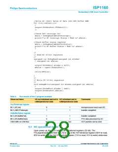
Table 6 shows the results after running this program.
9397 750 11371
© Koninklijke Philips Electronics N.V. 2003. All rights reserved.
Product data
Rev. 04 — 04 July 2003
26 of 88

 NXP [ NXP ]