ISP1160
Embedded USB Host Controller
Philips Semiconductors
• ATL buffer length = 400H, ITL buffer length = 200H.
This is insufficient use of the internal FIFO buffer RAM.
• ATL buffer length = 1000H, ITL buffer length = 0H.
This will use the internal FIFO buffer RAM for only ATL transfers.
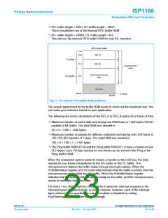
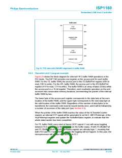
FIFO buffer RAM
top
ITL0
ISO_A
ISO_B
ITL buffer
ATL buffer
ITL1
programmable
sizes
control/bulk/interrupt
data
ATL
not used
bottom
4 kbytes
MGT950
Fig 17. HC internal FIFO buffer RAM partitions.
The actual requirement for the buffer RAM needs to reach not the maximum size. You
can make your selection based on your application.
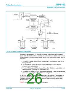
The following are some calculations of the ISO_A or ISO_B space for a frame of data:
• Maximum number of useful data sent during one USB frame is 1280 bytes (20 ISO
packets of 64 bytes). The total RAM size needed is:
20 × 8 + 1280 = 1440 bytes.
• Maximum number of packets for different endpoints sent during one USB frame is
150 (150 ISO packets of 1 byte). The total RAM size needed is:
150 × 8 + 150 × 1 = 1350 bytes.
• The Ping buffer RAM (ITL0) and the Pong buffer RAM (ITL1) have a maximum size
of 2 kbytes each. All data needed for one frame can be stored in the Ping or the
Pong buffer RAM.
When the embedded system wants to initiate a transfer to the USB bus, the data
needed for one frame is transferred to the ATL buffer or the ITL buffer. The
microprocessor detects the buffer status through interrupt routines. When the
HcBufferStatus register (2CH to read only) indicates that the buffer is empty, then the
microprocessor writes data into the buffer. When the HcBufferStatus register
indicates that the buffer is full, the data is ready on the buffer, and the microprocessor
needs to read data from the buffer.
For every 1 ms, there might be many events to generate interrupt requests to the
microprocessor for data transfer or status retrieval. However, each of the interrupt
types defined in this specification can be enabled or disabled by setting
HcµPInterruptEnable register bits accordingly.
9397 750 11371
© Koninklijke Philips Electronics N.V. 2003. All rights reserved.
Product data
Rev. 04 — 04 July 2003
23 of 88

 NXP [ NXP ]