ISP1160
Embedded USB Host Controller
Philips Semiconductors
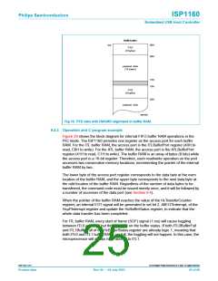
the end of the frame for full-speed and low-speed packets. By programming these
fields, the effective USB bus usage can be changed. Furthermore, the size of the ITL
buffers (HcITLBufferLength, 2AH to read, AAH to write) is programmed.
If a USB frame contains both ISO and AT packets, two interrupts will be generated
per frame.
One interrupt is issued concurrently with the SOF. This interrupt (ITLInt is set in the
HcµPInterrupt register) triggers reading and writing of the ITL buffer by the
microprocessor, after which the interrupt is cleared by the microprocessor.
Next the programmable ATL Interrupt (bit ATLInt is set in the HcµPInterrupt register)
is issued, which triggers reading and writing of the ATL buffer by the microprocessor,
after which the interrupt is cleared by the microprocessor. If the microprocessor
cannot handle the ISO interrupt before the next ISO interrupt, disrupted ISO traffic
can result.
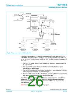
To be able to send more than one packet to the same Control or Bulk endpoint in the
same frame, the Active bit and the TotalBytes field are introduced (see Table 5).
Bit Active is cleared only if all data of the Philips Transfer Descriptor (PTD) have been
transferred or if a transaction at that endpoint contained a fatal error. If all PTDs of the
ATL are serviced once and the frame is not over yet, the HC starts looking for a PTD
with bit Active still set. If such a PTD is found and there is still enough time in this
frame, another transaction is started on the USB bus for this endpoint.
For ISO processing, the HCD also has to take care of the BufferStatus register
(2CH, read only) for the ITL buffer RAM operations. After the HCD writes ISO data
into ITL buffer RAM, the ITL0BufferFull or ITL1BufferFull bit (depending on whether it
is ITL0 or ITL1) will be set to logic 1.
After the HC processes the ISO data in the ITL buffer RAM, the corresponding
ITL0BufferDone or ITL1BufferDone bit will automatically be set to logic 1.
The HCD can clear the buffer status bits by a read of the ITL buffer RAM. This must
be done within the 1 ms frame from which ITL0BufferDone or ITL1BufferDone was
set. Failure to do so will cause the ISO processing to stop and a power-on reset or
software reset will have to be applied to the HC, a USB reset to the USB bus must
not be made.
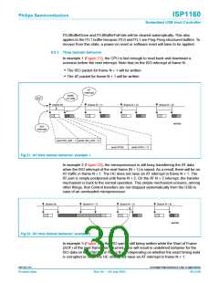
For example, the HCD writes ISO_A data into the ITL0 buffer in the first frame. This
will cause the HcBufferStatus register to show that the ITL0 buffer is full by setting
bit ITL0BufferFull to logic 1. At this stage, the HCD cannot write ISO data into the
ITL0 buffer RAM again.
In the second frame, the HC will process the ISO_A data in the ITL0 buffer. At the
same time, the HCD can write ISO_B data into the ITL1 buffer. When the next SOF
comes (the beginning of the third frame), both ITL1BufferFull and ITL0BufferDone are
automatically set to logic 1.
In the third frame, the HCD has to read at least two bytes (one word) of the ITL0
buffer to clear both the ITL0BufferFull and ITL0BufferDone bits. If both are not
cleared, when the next SOF comes (the beginning of the fourth frame) the
9397 750 11371
© Koninklijke Philips Electronics N.V. 2003. All rights reserved.
Product data
Rev. 04 — 04 July 2003
29 of 88

 NXP [ NXP ]