ISP1160
Embedded USB Host Controller
Philips Semiconductors
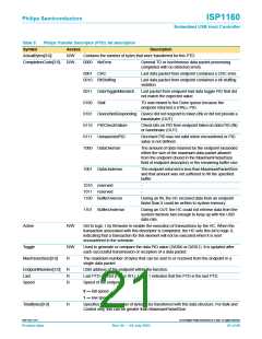
Table 5:
Philips Transfer Descriptor (PTD): bit description…continued
Symbol
Access
Description
DirectionPID[1:0]
R
00
01
10
11
SETUP
OUT
IN
reserved
B5_5
R/W
This bit is logic 0 at power-on reset. When this feature is not used, software used for the
ISP1160 is the same for the ISP1161 and the ISP1161A. When this bit is set to logic 1 in
this PTD for interrupt endpoint transfer, only one PTD USB transaction will be sent out in
1 ms.
Format
R
R
The format of this data structure. If this is a Control, Bulk or Interrupt endpoint, then
Format = 0. If this is an Isochronous endpoint, then Format = 1.
FunctionAddress[6:0]
This is the USB address of the function containing the endpoint that this PTD refers to.
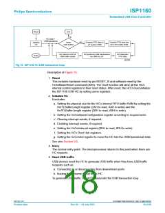
9.4 HC’s internal FIFO buffer RAM structure
9.4.1 Partitions
According to the Universal Serial Bus Specification Rev. 2.0, there are four types of
USB data transfers: Control, Bulk, Interrupt and Isochronous.
The HC’s internal FIFO buffer RAM has a physical size of 4 kbytes. This internal FIFO
buffer RAM is used for transferring data between the microprocessor and USB
peripheral devices. This on-chip buffer RAM can be partitioned into two areas:
Acknowledged Transfer List (ATL) buffer and Isochronous (ISO) Transfer List (ITL)
buffer. The ITL buffer is a Ping-Pong structured FIFO buffer RAM that is used to keep
the payload data and their PTD header for Isochronous transfers. The ATL buffer is a
non Ping-Pong structured FIFO buffer RAM that is used for the other three types of
transfers.
The ITL buffer can be further partitioned into ITL0 and ITL1 for the Ping-Pong
structure. The ITL0 and ITL1 buffers always have the same size. The microprocessor
can put ISO data into either the ITL0 buffer or the ITL1 buffer. When the
microprocessor accesses an ITL buffer, the HC can take over the other ITL buffer at
the same time. This architecture improves the ISO transfer performance.
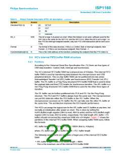
The HCD can assign the logical size for the ATL buffer and ITL buffers at any time, but
normally at initialization after power-on reset. This is done by setting the
HcATLBufferLength register (2BH to read, ABH to write) and the HcITLBufferLength
register (2AH to read, AAH to write), respectively. The total length (ATL buffer + ITL
buffer) should not exceed the maximum RAM size of 4 kbytes. Figure 17 shows the
partitions of the internal FIFO buffer RAM. When assigning buffer RAM sizes, follow
this formula:
ATL buffer length + 2 × (ITL buffer size) ≤ 1000H (that is, 4 kbytes)
where: ITL buffer size = ITL0 buffer length = ITL1 buffer length
The following assignments are examples of legal uses of the internal FIFO buffer
RAM:
• ATL buffer length = 800H, ITL buffer length = 400H.
This is the maximum use of the internal FIFO buffer RAM.
9397 750 11371
© Koninklijke Philips Electronics N.V. 2003. All rights reserved.
Product data
Rev. 04 — 04 July 2003
22 of 88

 NXP [ NXP ]