ISP1160
Embedded USB Host Controller
Philips Semiconductors
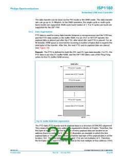
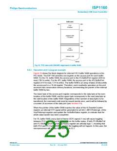
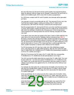
RAM buffer
top
00H
08H
PTD
(8 bytes)
payload data
(14 bytes)
15H
18H
PTD
(8 bytes)
20H
payload data
MGT953
Fig 19. PTD data with DWORD alignment in buffer RAM.
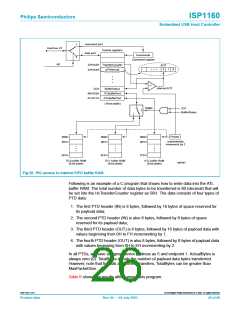
9.4.3 Operation and C program example
Figure 20 shows the block diagram for internal FIFO buffer RAM operations in the
PIO mode. The ISP1160 provides one register as the access port for each buffer
RAM. For the ITL buffer RAM, the access port is the ITLBufferPort register (40H to
read, C0H to write). For the ATL buffer RAM, the access port is the ATLBufferPort
register (41H to read, C1H to write). The buffer RAM is an array of bytes (8 bits) while
the access port is a 16-bit register. Therefore, each read/write operation on the port
accesses two consecutive memory locations, incrementing the pointer of the internal
buffer RAM by two.
The lower byte of the access port register corresponds to the data byte at the even
location of the buffer RAM, and the upper byte corresponds to the next data byte at
the odd location of the buffer RAM. Regardless of the number of data bytes to be
transferred, the command code must be issued merely once, and it will be followed by
a number of accesses of the data port (see Section 8.4).
When the pointer of the buffer RAM reaches the value of the HcTransferCounter
register, an internal EOT signal will be generated to set bit 2, AllEOTInterrupt, of the
HcµPInterrupt register and update the HcBufferStatus register, to indicate that the
whole data transfer has been completed.
For ITL buffer RAM, every start of frame (SOF) signal (1 ms) will cause toggling
between ITL0 and ITL1 but this depends on the buffer status. If both ITL0BufferFull
and ITL1BufferFull of the HcBufferStatus register are already logic 1, meaning that
both ITL0 and ITL1 buffer RAMs are full, the toggling will not happen. In this case, the
microprocessor will always have access to ITL1.
9397 750 11371
© Koninklijke Philips Electronics N.V. 2003. All rights reserved.
Product data
Rev. 04 — 04 July 2003
25 of 88

 NXP [ NXP ]