PFS122
8bit MTP MCU with 12-bit R-Type ADC
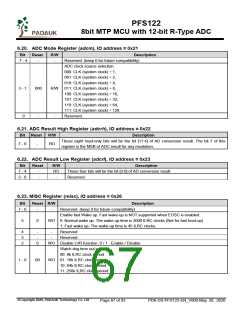
6.6. Timer16 mode Register (t16m), IO address = 0x06
Bit
Reset R/W
Description
Timer16 Clock source selection.
000: disable
001: CLK (system clock)
010: reserved
7 - 5
000
R/W 011: PA4 falling edge (from external pin)
100: IHRC
101: EOSC
110: ILRC
111: PA0 falling edge (from external pin)
Timer16 clock pre-divider.
00: ÷1
4 - 3
00
R/W 01: ÷4
10: ÷16
11: ÷64
Interrupt source selection. Interrupt event happens when the selected bit status is changed.
0 : bit 8 of Timer16
1 : bit 9 of Timer16
2 : bit 10 of Timer16
R/W 3 : bit 11 of Timer16
4 : bit 12 of Timer16
5 : bit 13 of Timer16
6 : bit 14 of Timer16
7 : bit 15 of Timer16
2 - 0
000
6.7. External Oscillator setting Register (eoscr), IO address = 0x0a
Bit
Reset R/W
Description
7
0
WO Enable external crystal oscillator. 0 / 1 : Disable / Enable
External crystal oscillator selection.
00 : reserved
6 - 5
00
WO 01 : Low driving capability, for lower frequency, ex: 32KHz crystal oscillator
10 : Middle driving capability, for middle frequency, ex: 1MHz crystal oscillator
11 : High driving capability, for higher frequency, ex: 4MHz crystal oscillator
4 - 1
0
-
-
Reserved. Please keep 0 for future compatibility.
0
WO Power-down the Bandgap and LVR hardware modules. 0 / 1: normal / power-down.
©Copyright 2020, PADAUK Technology Co. Ltd
Page 63 of 93
PDK-DS-PFS122-EN_V000-May 28, 2020

 PADAUK [ PADAUK Technology ]