PFS122
8bit MTP MCU with 12-bit R-Type ADC
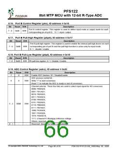
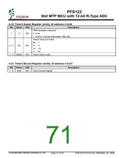
6.20. ADC Mode Register (adcm), IO address = 0x21
Bit
Reset
R/W
Description
Reserved. (keep 0 for future compatibility)
7 - 4
-
-
ADC clock source selection.
000: CLK (system clock) ÷ 1,
001: CLK (system clock) ÷ 2,
010: CLK (system clock) ÷ 4,
011: CLK (system clock) ÷ 8,
100: CLK (system clock) ÷ 16,
101: CLK (system clock) ÷ 32,
110: CLK (system clock) ÷ 64,
111: CLK (system clock) ÷ 128
Reserved.
3 - 1
000
R/W
0
-
-
6.21. ADC Result High Register (adcrh), IO address = 0x22
Bit Reset
R/W
Description
These eight read-only bits will be the bit [11:4] of AD conversion result. The bit 7 of this
register is the MSB of ADC result for any resolution.
7 - 0
-
RO
6.22. ADC Result Low Register (adcrl), IO address = 0x23
Bit
Reset
R/W
RO
-
Description
These four bits will be the bit [3:0] of AD conversion result.
Reserved
7 - 4
3 - 0
-
-
6.23. MISC Register (misc), IO address = 0x26
Bit
Reset R/W
Description
Reserved. (keep 0 for future compatibility)
Enable fast Wake up. Fast wake-up is NOT supported when EOSC is enabled.
7 - 6
-
-
5
0
WO 0: Normal wake up. The wake-up time is 3000 ILRC clocks (Not for fast boot-up)
1: Fast wake up. The wake-up time is 45 ILRC clocks.
4
3
2
-
-
-
-
Reserved.
Reserved.
0
WO Disable LVR function. 0 / 1 : Enable / Disable
Watch dog time out period
00: 8k ILRC clock period
1 - 0
00
WO 01: 16k ILRC clock period
10: 64k ILRC clock period
11: 256k ILRC clock period
©Copyright 2020, PADAUK Technology Co. Ltd
Page 67 of 93
PDK-DS-PFS122-EN_V000-May 28, 2020

 PADAUK [ PADAUK Technology ]