OXCB950
OXFORD SEMICONDUCTOR LTD.
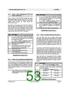
8.1.2 Zone1 : Power Management DATA and
DATA_SCALE zone
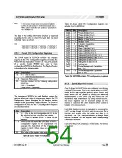
Bits Description
15
‘0’ = There are no more Configuration WORDs
to follow in Zone2. Move to the next available
zone or end EEPROM program if no more zones
are enabled in the Header.
Zone 1 region of the EEPROM provides the power
management registers with user values for the DATA and
DATA_SCALE fields, that will be provided to the system
software when requests are made through the
DATA_SELECT field.
‘1’ = There is another Configuration WORD to
follow for the Local Configuration Registers.
14:8 These seven bits define the byte-offset of the
Local configuration register to be programmed.
For example the byte-offset for LCC[23:16] is
0x02.
Since there are 16 possible values for the DATA_SELECT
fields, the system can request up to 16 sets of DATA and
DATA_SCALE values. The organisation of the EEPROM
data for this zone is shown in the table. Each DATA and
DATA_SCALE value being programmed is relevant to a
particular value of the DATA_SELECT parameter.
7:0 8-bit value of the register to be programmed
EEPROM Word Format for Zone 2
Bits Description
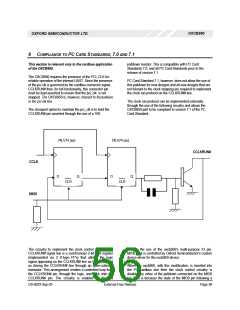
8.1.4 Zone 3 : Cardbus Information Structure
15
‘0’ = There are no more Configuration WORDs
to follow in Zone1. Move to the next available
zone or end EEPROM program if no more zones
are enabled in the Header.
This zone allows the user to provide custom tuple
information for the Cardbus Information Structure, overriding
the default hardcoded tuple values found in the device.
Downloading into this zone programs an internal RAM with
the user’s tuple data and automatically sets the source of
the cardbus information structure to be this RAM. This
process sets the local configuration register bit LCC(21) to
1.
‘1’ = There is another Configuration WORD to
follow for the Power Management Data zone.
Reserved. To be written as ‘0’
14
13:1 DATA SELECT
0
This indicates for which DATA_SELECT value
the DATA and DATA_SCALE values in this
particular word are associated with.
The format of the EEPROM organisation for this zone is
9:8 DATA SCALE Value
shown by the table. The first word indicates the number of
NOTE1
tuple data bytes to follow (in multiples of 2
) and the
For the Data Select Field in this word
subsequent words contain the actual tuple data-bytes to be
inserted into the cardbus information structure that will be
visible at Dword18 or 32 in the PCI configuration space.
7:0 DATA Register Value
For the Data Select Field in this word.
EEPROM Word Format for Zone 1
Tuple data bytes are interrogated until the specified
number of tuple data-bytes have been collected in which
case the EEPROM moves over to the next zone if it exists,
or the eeprom download terminates if no other zones are
present.
8.1.3 Zone2: Local Configuration Register Zone
The Zone2 region of EEPROM contains the program value
of the vendor-specific Local Configuration Registers using
one or more configuration WORDs. Registers are selected
using a 7-bit byte-offset field. This offset value is the offset
from Base Address Registers in I/O or memory space (see
section 6.4).
Description
st
1
NO of TUPLE bytes to follow, in binary.
WORD This sets a counter that will terminate download into
this zone when the correct number of Tuple Bytes
have been collected.
NOTE1
(Value to be in multiples of 2
)
Note: Not all of the registers in the Local Configuration Register set are
writable by EEPROM. The format of configuration WORDs for
the Local Configuration Registers in Zone1 are described in
the following table.
nd
2
Tuple Byte 1
Tuple Byte 3
Tuple Byte y+1
Tuple Byte 0
Tuple Byte 2
Tuple Byte y
WORD
3th
WORD
nth
WORD
EEPROM Word Format for Zone 3
DS-0033 Sep 05
External-Free Release
Page 53

 OXFORD [ OXFORD SEMICONDUCTOR ]