OXCB950
OXFORD SEMICONDUCTOR LTD.
8 SERIAL EEPROM SPECIFICATION
The OXCB950 can be configured using an optional serial
electrically-erasable programmable read only memory
(EEPROM). If the EEPROM is not present, the device will
remain in its default configuration after reset. Although this
may be adequate for some applications, many will benefit
from the degree of programmability afforded by this
feature. The EEPROM also allows accesses to the
integrated UART, which can be useful for default setups.
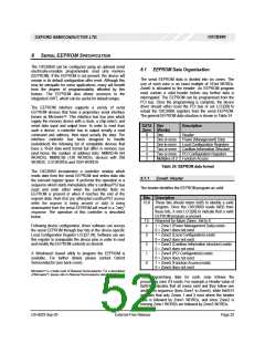
8.1 EEPROM Data Organisation
The serial EEPROM data is divided into six zones. The
size of each zone is an exact multiple of 16-bit WORDs.
Zone0 is allocated to the header. An EEPROM program
must contain a valid header before any further data is
interrogated. The EEPROM can be programmed from the
PCI bus. Once the programming is complete, the device
driver should either reset the PCI bus or set LCC[29] to
reload the OXCB950 registers from the serial EEPROM.
The general EEPROM data structure is shown in Table 24.
The EEPROM interface supports a variety of serial
EEPROM devices that have a proprietary serial interface
TM
known as Microwire . This interface has four pins which
supply the memory device with a clock, a chip-select, and
serial data input and output lines. In order to read from
such a device, a controller has to output serially a read
command and address, then input serially the data. The
interface controller has been designed to handle
(autodetect) the following list of compatible devices that
have a 16-bit data word format but differ in memory size
(and hence the number of address bits). NM93C46 (64
WORDS), NM93C56 (128 WORDS), devices with 256
WORDS, 512 WORDs and 1024 WORDS.
DATA Size
Description
Zone (Words)
0
1
2
3
4
5
One
Header
One or more Power (Management) Data
One to more Local Configuration Registers
Two or more Cardbus Information Structure
Two or more PCI Configuration Registers
Multiples of 2 Function Access
Table 24: EEPROM data format
The OXCB950 incorporates a controller module which
reads data from the serial EEPROM and writes data into
the relevant register space. It performs this operation in a
sequence which starts immediately after a cardbus/PCI bus
reset and ends either when the controller finds no
EEPROM is present or when it reaches the end of the
eeprom data. Note that any attempted cardbus/PCI access
while the eeprom is being sensed or data is being
downloaded from the serial EEPROM will result in a “retry”
response. The operation of this controller is described
below.
8.1.1 Zone0: Header
The header identifies the EEPROM program as valid.
Bits Description
15:8 These bits should return 0xB5 to identify a valid
program. Once the OXCB950 reads 0xB5 from
these bits, it sets LCC[28] to indicate that a valid
EEPROM program is present.
7:5 Reserved for future Zones. Set to 0.
4
3
2
1
0
1 = Zone1 (Power Management Data) exists
0 = Zone1 does not exist
Following device configuration, driver software can access
the serial EEPROM through four bits in the device-specific
Local Configuration Register LCC[27:24]. Software can use
this register to manipulate the device pins in order to read
and modify the EEPROM contents as desired.
1 = Zone2 (Local Configuration) exists
0 = Zone2 does not exist
1 = Zone3 (Cardbus Information structure) exists
0 = Zone3 does not exist
A Windows based utility to program the EEPROM is
available. For further details please contact Oxford
Semiconductor (see back cover).
1 = Zone4 (PCI Configuration) exists
0 = Zone4 does not exist
1 = Zone5 (Function Access) exists
0 = Zone5 does not exist
TM
Microwire is a trade mark of National Semiconductor. For a description
TM
of Microwire , please refer to National Semiconductor data manuals.
The programming data for each zone follows the
proceeding zone if it exists. For example a Header value of
0xB51F indicates that all zones exist and they follow one
another in sequence (from Zone1 to Zone5), while 0xB514
indicates that only Zones 1 and 3 exist where the header
data is followed by Zone1 WORDs, and since Zone2 is
missing Zone1 WORDs are followed by Zone3 WORDs.
DS-0033 Sep 05
External-Free Release
Page 52

 OXFORD [ OXFORD SEMICONDUCTOR ]