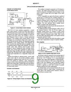
NCV5171
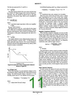
Reducing the Current Limit
In some applications, the designer may prefer a lower
limit on the switch current than 1.5 A. An external shunt can
Another solution to the current limiting problem is to
externally measure the current through the switch using a
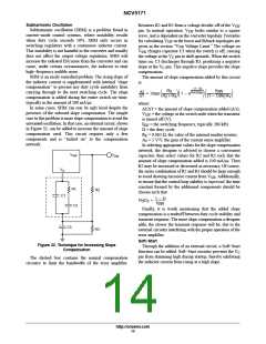
sense resistor. Such a circuit is illustrated in Figure 31.
be connected between the V pin and ground to reduce its
C
clamp voltage. Consequently, the current limit of the
internal power transistor current is reduced from its nominal
value.
V
CC
The voltage on the V pin can be evaluated with the
equation
C
V
PGND
AGND
C
+
−
V
IN
V
+ I
R A
SW E V
C
where:
R = .063W, the value of the internal emitter resistor;
R1
C2
E
C1
A = 5 V/V, the gain of the current sense amplifier.
V
R2
C3
Q1
Since R and A cannot be changed by the end user, the
E
V
only available method for limiting switch current below
Output
Ground
1.5 A is to clamp the V pin at a lower voltage. If the
R
SENSE
C
maximum switch or inductor current is substituted into the
equation above, the desired clamp voltage will result.
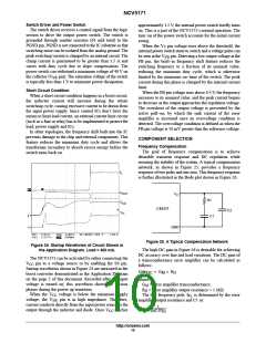
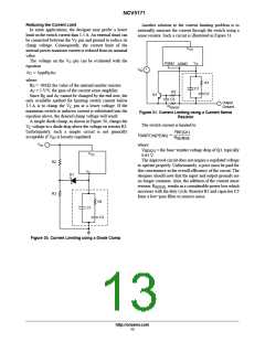
A simple diode clamp, as shown in Figure 30, clamps the
Figure 31. Current Limiting using a Current Sense
Resistor
The switch current is limited to
V voltage to a diode drop above the voltage on resistor R3.
C
V
Unfortunately, such a simple circuit is not generally
BE(Q1)
I
+
SWITCH(PEAK)
acceptable if V is loosely regulated.
R
IN
SENSE
V
where:
IN
V
0.65 V.
= the base−emitter voltage drop of Q1, typically
BE(Q1)
V
CC
The improved circuit does not require a regulated voltage
to operate properly. Unfortunately, a price must be paid for
this convenience in the overall efficiency of the circuit. The
designer should note that the input and output grounds are
no longer common. Also, the addition of the current sense
R2
R3
V
C
D1
resistor, R
, results in a considerable power loss which
SENSE
increases with the duty cycle. Resistor R2 and capacitor C3
form a low−pass filter to remove noise.
R1
C1
C2
Figure 30. Current Limiting using a Diode Clamp
http://onsemi.com
13

 ONSEMI [ ONSEMI ]