NCV5171
Subharmonic Oscillation
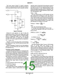
Resistors R2 and R3 form a voltage divider off of the V
SW
Subharmonic oscillation (SHM) is a problem found in
current−mode control systems, where instability results
when duty cycle exceeds 50%. SHM only occurs in
switching regulators with a continuous inductor current.
This instability is not harmful to the converter and usually
does not affect the output voltage regulation. SHM will
increase the radiated EM noise from the converter and can
cause, under certain circumstances, the inductor to emit
high−frequency audible noise.
pin. In normal operation, V
looks similar to a square
SW
wave, and is dependent on the converter topology. Formulas
for calculating V in the boost and flyback topologies are
SW
given in the section “V Voltage Limit.” The voltage on
SW
V
SW
charges capacitor C3 when the switch is off, causing
the voltage at the V pin to shift upwards. When the switch
C
turns on, C3 discharges through R3, producing a negative
slope at the V pin. This negative slope provides the slope
C
compensation.
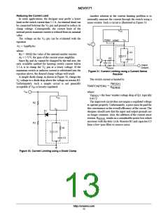
SHM is an easily remedied problem. The rising slope of
the inductor current is supplemented with internal “slope
compensation” to prevent any duty cycle instability from
carrying through to the next switching cycle. The slope
compensation is added during the entire switch on−time,
typically in the amount of 180 mA/ms.
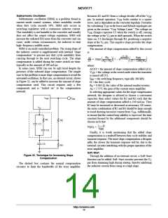
In some cases, SHM can rear its ugly head despite the
presence of the onboard slope compensation. The simple
cure to this problem is more slope compensation to avoid the
unwanted oscillation. In that case, an external circuit, shown
in Figure 32, can be added to increase the amount of slope
compensation used. This circuit requires only a few
components and is “tacked on” to the compensation
network.
The amount of slope compensation added by this circuit
is:
*(1*D)
R
f
3
SW
(1 * D)R A
E V
DI
DT
R C f
3 SW
3
SW ǒ
+ V
Ǔ
ǒ1 * e Ǔǒ
Ǔ
R )R
2 3
where:
DI/DT = the amount of slope compensation added (A/s);
= the voltage at the switch node when the transistor
V
SW
is turned off (V);
= the switching frequency, typically 280 kHz
f
SW
D = the duty cycle;
R = 0.063 W, the value of the internal emitter resistor;
E
A = 5 V/V, the gain of the current sense amplifier.
V
In selecting appropriate values for the slope compensation
network, the designer is advised to choose a convenient
capacitor, then select values for R2 and R3 such that the
amount of slope compensation added is 100 mA/ms. Then
R2 may be increased or decreased as necessary. Of course,
the series combination of R2 and R3 should be large enough
V
V
SW
SW
V
C
to avoid drawing excessive current from V . Additionally,
SW
to ensure that the control loop stability is improved, the time
constant formed by the additional components should be
chosen such that
R1
R2
C1
1 * D
R C
3 3
t
f
SW
C2
Finally, it is worth mentioning that the added slope
compensation is a tradeoff between duty cycle stability and
transient response. The more slope compensation a designer
adds, the slower the transient response will be, due to the
external circuitry interfering with the proper operation of the
error amplifier.
C3
R3
Soft−Start
Figure 32. Technique for Increasing Slope
Compensation
Through the addition of an external circuit, a Soft−Start
function can be added. Soft−Start circuitry prevents the V
C
pin from slamming high during startup, thereby inhibiting
the inductor current from rising at a high slope.
The dashed box contains the normal compensation
circuitry to limit the bandwidth of the error amplifier.
http://onsemi.com
14

 ONSEMI [ ONSEMI ]