NCP3170
3.3 V
where:
C
CIN
= Output capacitor
= Output capacitor ESR
= Total delay interval
= Input Voltage
IN
ESR
t
DELAY_TOTAL
V
IN
Output
Voltage
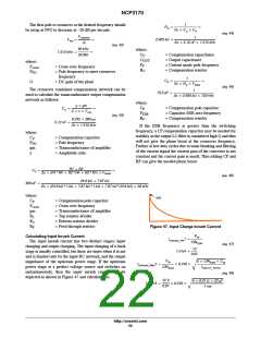
Once the t
has expired, the buck converter
DELAY_TOTAL
starts to switch and a second inrush current can be
calculated:
ǒ
Ǔ
COUT ) CLOAD VOUT
D
Output
Current
IOCinrush_RMS
+
) ICL D
(eq. 49)
Ǹ
tSS
3
where:
tss
C
C
= Total converter output capacitance
= Total load capacitance
= Duty ratio of the load
= Applied load at the output
= RMS inrush current during start-up
= Soft start interval
OUT
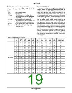
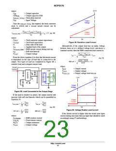
Figure 49. Resistive Load Current
LOAD
D
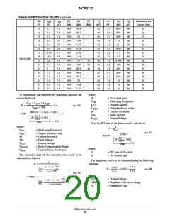
Alternatively, if the output load has an under voltage
lockout, turns on at a defined voltage level, and draws a
constant current, then the RMS connected load current is:
I
I
t
CL
OCinrush_RMS
SS
VOUT * VOUT_TO
V
OUT
= Output voltage
+ Ǹ
ICL1
IOUT
VOUT
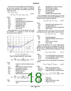
From the above equation, it is clear that the inrush current
is dependent on the type of load that is connected to the
output. Two types of load are considered in Figure 48: a
resistive load and a stepped current load.
(eq. 51)
3.3 V * 2.5 V
492 mA +
Ǹ
1 A
3.3 V
where:
Inrush
Current
I
= Output current
= Output voltage
= Output voltage load turn on
OUT
Load
V
V
OUT
OUT_TO
OR
1.0 V
3.3 V
Output
Voltage
Figure 48. Load Connected to the Output Stage
If the load is resistive in nature, the output current will
increase with soft start linearly which can be quantified in
Equation 50.
Output
Current
VOUT
VOUT
1
ICLR_RMS
+
ICR_PK +
t
Ǹ
ROUT
ROUT
3
tss
(eq. 50)
3.3 V
3.3 V
1
Figure 50. Voltage Enable Load Current
191 mA +
300 mA +
Ǹ
10 W
10 W
3
If the inrush current is higher than the steady state input
current during max load, then an input fuse should be rated
where:
2
I
I
= RMS resistor current
= Peak resistor current
= Output resistance
= Output voltage
accordingly using I t methodology.
CLR_RMS
CR_PK
R
OUT
V
OUT
http://onsemi.com
23

 ONSEMI [ ONSEMI ]