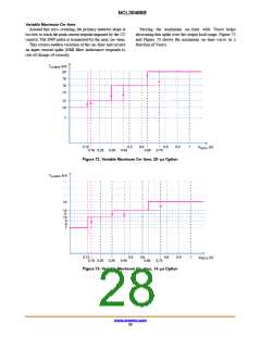
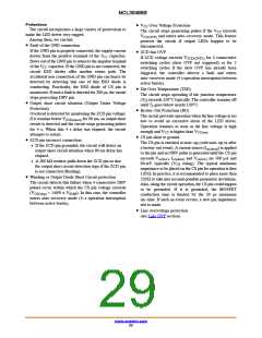
NCL30486B
Protections
• V Over Voltage Protection
CC
The circuit incorporates a large variety of protections to
make the LED driver very rugged.
Among them, we can list:
The circuit stops generating pulses if the V exceeds
CC
V
and enters auto−recovery mode. This feature
CC(OVP)
protects the circuit if output LEDs happen to be
disconnected.
• Fault of the GND connection
If the GND pin is properly connected, the supply current
• ZCD fast OVP
drawn from the positive terminal of the V capacitor,
flows out of the GND pin to return to the negative terminal
CC
If ZCD voltage exceeds V
for 4 consecutive
ZCD(OVP2)
switching cycles (slow OVP not triggered) or for 2
switching cycles if the slow OVP has already been
triggered, the controller detects a fault and enters
auto−recovery mode (4 s operation interruption between
active bursts).
of the V capacitor. If the GND pin is not connected, the
CC
circuit ESD diodes offer another return path. The
accidental non connection of the GND pin can hence be
detected by detecting that one of this ESD diode is
conducting. Practically, the ESD diode of CS pin is
monitored. If such a fault is detected for 200 ms, the circuit
stops generating DRV pin.
• Die Over Temperature (TSD)
The circuit stops operating if the junction temperature
(T ) exceeds 150°C typically. The controller remains off
J
• Output short circuit situation (Output Under Voltage
until T goes below nearly 130°C.
J
Protection)
• Brown−Out Protection (BO)
Overload is detected by monitoring the ZCD pin voltage:
if it remains below V
circuit is detected and the circuit stops generating pulses
for 4 s. When this 4 s delay has elapsed, the circuit
attempts to restart.
The circuit prevents operation when the line voltage is too
low to avoid an excessive stress of the LED driver.
Operation resumes as soon as the line voltage is high
for 90 ms, an output short
ZCD(short)
enough and V is higher than V
.
CC
CC(on)
• CS pin short to ground
• ZCD pin incorrect connection:
The CS pin is checked at start−up (cold start−up or after
♦ If the ZCD pin grounded, the circuit will detect an
output short circuit situation when 90 ms delay has
elapsed.
a brown−out event). A current source (I
) is applied
cs(short)
to the pin and no DRV pulse is generated until the CS pin
exceeds V . I and V are 500 mA and
cs(low) cs(short)
cs(low)
♦ A 200 kW resistor pulls down the ZCD pin so that
the output short circuit detection trips if the ZCD pin
is not connected (floating).
60 mV typically (V rising). The typical minimum
CS
impedance to be placed on the CS pin for operation is then
120 W. In practice, it is recommended to place more than
250W to take into account possible parametric deviations.
Also, along the circuit operation, the CS pin could happen
to be grounded. If it is grounded, the MOSFET
conduction time is limited by the 20 ms maximum
on−time. If such an event occurs, a new pin impedance
test is made.
• Winding or Output Diode Short Circuit protection
The circuit detects this failure when 4 consecutive DRV
pulses occur within which the CS pin voltage exceeds
(V
= 140% x V
). In this case, the controller
CS(stop)
ILIM
enters auto−recovery mode (4−s operation interruption
between active bursts).
• Line overvoltage protection
(see Line OVP section)
www.onsemi.com
29

 ONSEMI [ ONSEMI ]