H8PS
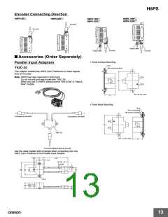
Accessories (Order Separately)
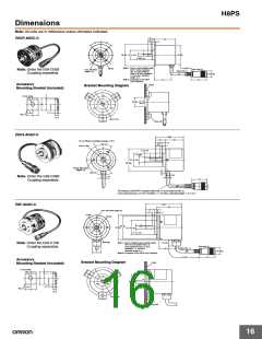
E69-C06B Shaft Coupling (for the E6CP)
E69-C08B Shaft Coupling (for the E6C3)
E69-C10B Shaft Coupling (for the E6F)
26.2
(12)
(19)
23.6
22
Four, M4 Hexagon
socket-head setscrews
6.8
6.8
7.1
7.1
5.5
5.5
Four, M4 Hexagon
socket-head setscrews
(11)
Four, M3 Hexagon
socket-head setscrews
3.6
3.6
2.8
3.5
3.5
2.8
(16.4)
8H8 dia.
8H8 dia.19 dia.
6H8 dia.15 dia.
10H8 dia.22 dia.
Note: The material is fiber-glass-reinforced
Note: The material is fiber-glass-reinforced
Note: The material is fiber-glass-reinforced
polybutylene terephthalate resin (PBT).
polybutylene terephthalate resin (PBT).
polybutylene terephthalate resin (PBT).
E69-DF5 Extension Cable
34.6
5,000
37
16.9 dia.
16.9 dia.
(See note 1.)
(See note 2.)
(See note 3.)
Note 1: E6F-AG5C-C, E6CP-AG5C-C, and E6C3-AG5C-C Connectors for the H8PS.
Note 2: 6-dia., 12-core shielded cable (cross-sectional area: 0.2 mm2, insulation: 1.1 mm dia.), standard length: 5 m
Note 3: Connected to the H8PS Cam Positioner.
Note: Refer to Characteristics on page 4 for the maximum cable length.
The following models are also available: E69-DF10 (10 m), E69-DF15 (15 m), E69-DF20 (20 m), and E69-DF98 (98 m).
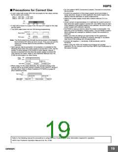
Safety Precautions for Encoders
■ Precautions for Correct Use
• Do not subject the E6CP Encoder to oil or water.
• The Encoder consists of high-precision components. Handle it with
utmost care and do not drop it, otherwise malfunctioning may
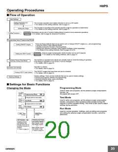
Mounting Procedure
Do not secure the
Coupling and shaft
with screws at this
time.
1
Insert the shaft into the Coupling.
result.
• When connecting the shaft of the Encoder with a chain timing belt
or gear, connect the chain timing belt or gear with the shaft via a
bearing or coupling as shown in the following diagram.
2
Secure the Encoder.
Chain
sprocket
Coupling
Bearings
Rotary Encoder
Refer to the table for
the maximum
insertion lengths of
the shaft into the
Coupling.
Coupling
E69-C06B
E69-C08B
E69-C10B
Maximum insertion length
5.5 mm
6.8 mm
7.1 mm
3
Secure the Coupling.
• If the decentering or declination value exceeds the tolerance, an
excessive load imposed on the shaft may damage or shorten the
life of the Encoder.
Coupling
Tightening torque
• Do not place excessive loads on the shaft if the shaft is connected
to a gear.
E69-C06B 0.25 N·m
E69-C08B 0.44 N·m
E69-C10B 0.44 N·m
• The tightening torque must not exceed the value given in the table
at the right when the Rotary Encoder is mounted with screws.
• Do not pull wires with a force greater than 29.4 N while the Rotary
Encoder is secured and wired.
Be sure to turn
OFF the Encoder
before connecting
the lines.
4
5
Connect the power and I/O lines.
Rotary Encoder
Turn ON the power and check the
outputs.
29.4 N max.
Fastening
plate
Cord
• Do not subject the shaft to shock. Therefore, do not strike the shaft
or coupling with a hammer when inserting the shaft into the
coupling.
• Make sure there is no foreign matter in the Connector before
connecting it to the Encoder.
17

 OMRON [ OMRON ELECTRONICS LLC ]