H8PS
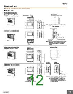
Dimensions
Note: All units are in millimeters unless otherwise indicated.
10
8
E6CP-AG5C-C
5
50
3
45°
45°
1
0
56 dia. 25−0.2 dia.
50 dia.
−0.008
−0.020
6
dia.
Note 1: Round, vinyl-insulated cable
with 10 cores (external
2,000
(See note 1.)
38 dia.
(See note 2.)
Four, M4 holes
(depth: 10)
Note: Order the E69-C06B
dia.: 6, cross-sectional
Coupling separately.
2
area: 0.18 mm , insulation:
16.9 dia.
1.0 mm dia.), standard
length: 2 m
Note 2: Connector to the H8PS
40
37
Cam Positioner.
Accessory
Mounting Bracket (Included)
Panel
Bracket Mounting Diagram
2
120°
5.5 dia. holes
25 dia.
(18) 16
9
120°
120°
3.1+0.1
8
0
Two, C1
16
(5.1)
68 0.2 dia.
Three, M5
E6C3-AG5C-C
(58)
5
20
38
D cut: Phase-Z position (range: 15°)
(15)
10
120° 0.1
1
40 0.1 dia.
+0
8−0.018 dia.
12 dia.
1
+0
30−0.021 dia.
50 dia.
Three, M4 holes
(depth: 5)
6
120° 0.1
8.8
Note: Order the E69-C08B
10
6
37
Coupling separately.
Oil-resistant, shield PVC-insulated cable with 12 cores (external dia.: 6,
2
cross-sectional area: 0.2 mm , insulation: 1.1 mm dia.), standard length: 1 m or 2 m
(85)
60
E6F-AG5C-C
20
15
5
Four, M3 holes (depth: 6)
48 dia.
3
3
24 dia.
54 dia.
60 dia.
1
0
40−0.025 dia.
0
10−0.015 dia.
Bearings
Note 1: Round, shielded vinyl-insulated cable
14 max.
42.5
Note: Order the E69-C10B
with 12 cores (external dia.: 6,
2
(See note 2.)
cross-sectional area: 0.2 mm ,
Coupling separately.
(See note 1.)
2,000
insulation: 1.1 mm dia.),
standard length: 2 m
16.9 dia.
17
Note 2: Connector to the H8PS Cam Positioner
37
Accessory
Mounting Bracket (included)
Panel
Bracket Mounting Diagram
2
5.5 dia. holes
120°
(18) 16
9
40 dia.
120°
120°
+
0.1
8
3.1
0
Two, C1
16
(5.1)
72 0.2 dia.
Three, M5
16

 OMRON [ OMRON ELECTRONICS LLC ]