TJA1028
NXP Semiconductors
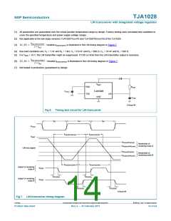
LIN transceiver with integrated voltage regulator
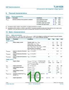
9. Thermal characteristics
Table 5.
Symbol
Rth(j-a)
Thermal characteristics
Parameter
Conditions
Typ
132
93
Unit
K/W
K/W
K/W
K/W
[1]
[2]
[1]
[2]
thermal resistance from junction to ambient
SO8; single-layer board
SO8; four-layer board
HVSON8; single-layer board
HVSON8; four-layer board
129
67
[1] According to JEDEC JESD51-2 and JESD51-3 at natural convection on 1s board.
[2] According to JEDEC JESD51-2, JESD51-5 and JESD51-7 at natural convection on 2s2p board. Board with two inner copper layers
(thickness: 35 μm) and thermal via array under the exposed pad connected to the first inner copper layer.
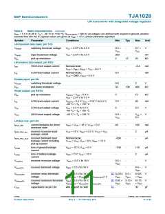
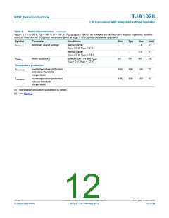
10. Static characteristics
Table 6.
Static characteristics
VBAT = 5.5 V to 28 V; Tvj = −40 °C to +150 °C; RL(LIN-VBAT) = 500 Ω; all voltages are defined with respect to ground; positive
currents flow into the IC; typical values are given at VBAT = 12 V; unless otherwise specified.
Symbol
Parameter
Conditions
Min
Typ
Max
Unit
Supply; pin VBAT
IBAT
battery supply current
Standby mode; VLIN = VBAT
Sleep mode; VLIN = VBAT
-
-
-
45
59
μA
μA
μA
12
18
Normal mode; bus recessive;
850
1800
VLIN = VBAT; VRXD = VCC; VRSTN = HIGH
Normal mode; bus dominant;
-
2.0
4.5
5.25
4.5
-
mA
V
VBAT = 12 V; VTXD = 0 V; VRSTN = HIGH
Vth(det)pon
Vth(det)poff
Vhys(det)pon
power-on detection threshold VBAT = 2 V to 28 V
voltage
-
-
-
-
power-off detection threshold VBAT = 2 V to 28 V
voltage
3
50
V
power-ondetection hysteresis VBAT = 2 V to 28 V
voltage
mV
Supply; pin VCC
VCC
supply voltage
VCC(nom) = 5 V; IVCC = −70 mA to 0 mA
4.9
5
5.1
V
V
VCC(nom) = 3.3 V; VBAT = 4.5 V to 28 V;
3.234
3.3
3.366
IVCC = −70 mA to 0 mA
IOlim
Vuvd
output current limit
VCC = 0 V to 5.5 V
VCC(nom) = 5 V
−250
4.5
-
-
-
-
-
-
−70
4.75
3.135
4.9
mA
V
undervoltage detection
voltage
VCC(nom) = 3.3 V
VCC(nom) = 5 V
2.97
4.6
V
Vuvr
undervoltage recovery
voltage
V
VCC(nom) = 3.3 V
3.036
-
3.234
5
V
[1]
[1]
R(VBAT-VCC)
resistance between pin VBAT VCC(nom) = 5 V; VBAT = 4.5 V to 5.5 V;
and pin VCC
Ω
IVCC = −70 mA to −5 mA;
regulator in saturation
Co
output capacitance
equivalent series resistance < 5 Ω
1.8
10
-
μF
TJA1028
All information provided in this document is subject to legal disclaimers.
© NXP B.V. 2011. All rights reserved.
Product data sheet
Rev. 2 — 25 February 2011
10 of 24

 NXP [ NXP ]