TDF8544
NXP Semiconductors
I2C-bus controlled 4 50 W power amplifier
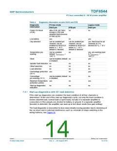
Table 4.
Diagnostic information on pins DIAG and STB
Diagnostic
information
I2C-bus mode
Legacy mode
DIAG pin
no
DIAG pin
STB pin
Power-On Reset
(POR)
after POR, pin DIAG
remains LOW until
amplifier starts (inverse
of start-up bit)
no
Low battery
yes
no
yes
Clip detection
can be enabled per
channel; can be
can be enabled per
channel; can be
yes; fixed level for all
channels at 2 %;
enabled by IB1[D7] if
below VP = 10 V;
default is ‘blocked’
enabled by IB1[D7] if
below VP = 10 V;
default is ‘blocked’
blocked for VP < 10 V
Temperature pre-
warning
can be enabled;
default: Tj(AV)(pwarn)
no
yes, pre-warning level
is Tj(AV)(pwarn) =
=
160 C
160 C
Short
can be enabled; default no
is enabled
yes
Speaker fault detection no
no
no
no
no
no
no
no
Offset detection
Load detection
no
no
Overvoltage protection yes
(20 V)
yes
Overvoltage
pre-warning (16 V)
can be enabled; default no
is disabled
no
Maximum temperature yes
protection (active)
no
yes
no
Start-up diagnostics
indication
no
no
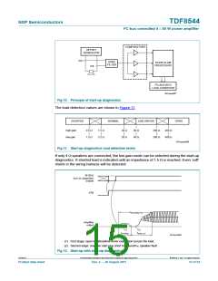
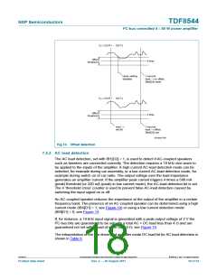
7.5.1 Start-up diagnostics with DC load detection
If the start-up diagnostics are enabled, the load condition of all four channels is
determined. At the end of the start-up diagnostics cycle, not only the load condition is
known (shorted load, normal load or open load), but also if a separate amplifier is
connected or if the outputs are shorted to battery or ground. If a separate amplifier
(booster) is detected, the amplifier can start-up in line driver mode (low gain setting).
The load diagnostic is insensitive to door-slam (slowly moving speaker due to slamming of
the car door) and to external interference such as crosstalk of relays switching in the
wiring harness; see Figure 10.
TDF8544
All information provided in this document is subject to legal disclaimers.
© NXP B.V. 2011. All rights reserved.
Product data sheet
Rev. 2 — 29 August 2011
14 of 54

 NXP [ NXP ]