®
Numonyx™ StrataFlash Embedded Memory (J3-65nm)
5.1
Reads
Reading from flash memory outputs stored information to the processor or chipset, and
does not change any contents. Reading can be performed an unlimited number of
times. Besides array data, other types of data such as device information or device
status are available from the flash.
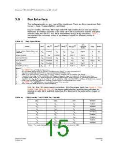
To perform a bus read operation, CEx (refer to Table 6 on page 15) and OE# must be
asserted. CEx is the device-select control; when active, it enables the flash memory
device. OE# is the data-output control; when active, the addressed flash memory data
is driven onto the I/O bus. For all read states, WE# and RP# must be de-asserted. See
Section 7.0, “Read operation” on page 21.
5.2
Writes
Writing or Programming to the device is where the host writes information or data into
the flash device for non-volatile storage. When the flash device is programmed, ‘ones’
are changed to ‘zeros’. ‘Zeros’ cannot be programmed back to ‘ones’. To do so, an erase
operation must be performed. Writing commands to the Command User Interface (CUI)
enables various modes of operation, including the following:
• Reading of array data
• Common Flash Interface (CFI) data
• Identifier codes, inspection, and clearing of the Status Register
• Block Erasure, Program, and Lock-bit Configuration (when VPEN = VPENH
)
Erasing is performed on a block basis – all flash cells within a block are erased together.
Any information or data previously stored in the block will be lost. Erasing is typically
done prior to programming. The Block Erase command requires appropriate command
data and an address within the block to be erased. The Byte/Word Program command
requires the command and address of the location to be written. Set Block Lock-Bit
commands require the command and block within the device to be locked. The Clear
Block Lock-Bits command requires the command and address within the device to be
cleared.
The CUI does not occupy an addressable memory location. It is written when the device
is enabled and WE# is active. The address and data needed to execute a command are
latched on the rising edge of WE# or the first edge of CE0, CE1, or CE2 that disables
the device (see Table 6 on page 15). Standard microprocessor write timings are used.
5.3
5.4
Output Disable
With CEx asserted, and OE# at a logic-high level (VIH), the device outputs are disabled.
Output signals D[15:0] are placed in a high-impedance state.
Standby
CE0, CE1, and CE2 can disable the device (see Table 6 on page 15) and place it in
standby mode. This manipulation of CEx substantially reduces device power
consumption. D[15:0] outputs are placed in a high-impedance state independent of
OE#. If deselected during block erase, program, or lock-bit configuration, the WSM
continues functioning, and consuming active power until the operation completes.
Datasheet
16
December 2008
319942-02

 NUMONYX [ NUMONYX B.V ]