FreesScPaI RlEeGISSTMeERCmS33Di3cE8S9oCRnIPdTuIOcNtor, Inc.
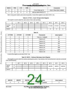
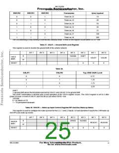
SWCR2
SWCR1
SWCR0
Comments
Timer on, t2
Timer on, t3
Timer on, t4
Timer on, t5
Timer on, t6
Timer on, t7
Timer on, t8
t(ms) typical
0
0
0
1
1
1
1
0
1
1
0
0
1
1
1
0
1
0
1
0
1
10
20
33
50
75
100
200
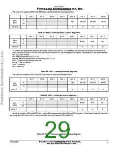
The SW watchdog is only running in Normal and Standby mode. A reset of this register occurs when RSTB = low
Table 37. GSLR — Ground Shift Level Register
This register is used to monitor the ground shift of the vehicle network.
r
BIT 7
BIT 6
BIT 5
BIT 4
BIT 3
BIT 2
BIT 1
GSLR1
0
BIT 0
GSLR0
0
R
TXDOM
SHIFT
GSLR
$00A
W
RESET
0
Table 38.
GSLR1
GSLR0
Typ GND Shift Level
0
0
1
1
0
1
0
1
0.7V
-1.2V
-1.7V
-2.2V
SHIFT
1=ground shift above the threshold selected by GSLR1 and GSLR2. 0=no ground shift
The SHIFT information is latched until a read operation of the GSLR register occurs. The GSLR register is set to 0 after
power on reset. A reset of GSLR1 and GSLR0 occurs when RSTB = low.
TXDOM
0 = no failure on TX
1 = TX permanent dominant
Table 39. WUICR — Wake-up Input Control Register/SPI And Bus Wake-up Status
This register is used to configure the wake up level for the L0, L1 and L2 inputs. in read operation it reports the CAN wake up
and SPI (csb) wake up events
.
BIT 7
BIT 6
BIT 5
BIT 4
BIT 3
BIT 2
BIT 1
WUICR1
0
BIT 0
WUICR0
0
R
SPIWU
BUSWU
WUICR
$00C
W
RESET
0
0
For More Information On This Product,
MC33389
MOTOROLA
25
Go to: www.freescale.com

 MOTOROLA [ MOTOROLA ]